I finally completed my Big-3 upgrade along with a 250A alternator and Sears platinum Group 35 battery. This project took me quite a bit of time to complete because of research, gathering of parts, and a lot of trial and error.
My goals that I wanted to attain:
- 250A alternator
- Fused alternator cable
- Big-3 upgrade with 1/0 gauge welding wire - color coded (red-positive, black-ground)
- Techflex braided sleeving - color coded (red-positive, black-ground)
- Adhesive lined, dual wall heat shrink - color coded (red-positive, black-ground)
- Crimp battery terminals
- Positive battery terminal protector
- Clean and efficient wiring
- Positive and ground busbars
- Re-locate remote voltage sense wire to positive busbar instead of OEM fuse block
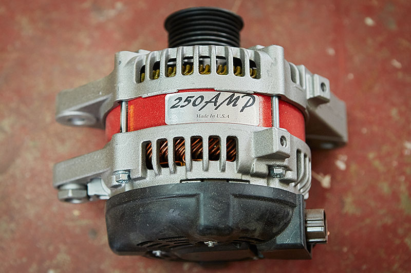
I began by buying a 250A alternator from a local shop near me called CAE that rebuilds Tacoma alternators using the stock part. They rebuilt the stator and rotor with more windings and then used a slightly smaller pulley to gain more RPM. All of this combined gives it the higher amperage. Also, because it's built from a stock alternator, the voltage regulator is original and the alternator bolts up without any spacers needed. On top of that, there is no core charge, so I was able to keep my stock alternator as a backup.
The next step was buying all of the parts, which were purchased from Remy Battery, Waytek Wire, Parts Express, Amazon, and Ballenger Motorsports.
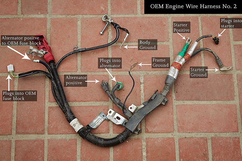
The first purchase was a stock "Engine Wire Harness No. 2". I found one online from a 2012 salvaged Tacoma through
TLS Auto Recycling, which matched identically to my 2015. My plan was to take it apart and only use what I needed. By doing this, I was able to take my time. If I had to use my original harness, then my truck would have sat immobile for a very long time.
As I disassembled the wiring harness, I learned a lot about how everything was connected. With this knowledge, I started to plan out how I was going to do this.
As I stated earlier, one of my goals was to relocate the remote voltage sense wire. The stock wiring harness already accomplishes remote sensing by reading voltage at the fuse block instead of at the battery or at the alternator itself. The reason to move its termination point to a different location was because I wanted to sense system voltage where I needed full voltage, which is at the positive busbar. In my new system, this is the main source of voltage for all accessories. This includes the OEM fuse block, my future fuse block, the battery, the winch, and anything else I might want to add. For more information regarding this subject, I highly recommend reading
The Alternator Bible at Billa Vista.
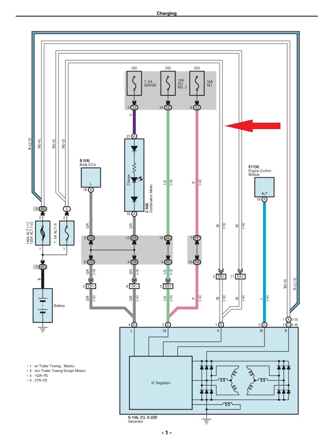
By looking at a schematic, I learned that the white wire at the alternator in the G2 connector is the voltage sense wire that I wanted to relocate.
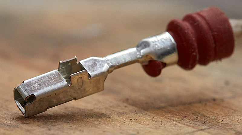
The following image shows the G2 connector that plugs into the alternator. My plan is to remove the voltage sense wire entirely from the harness. After that, I'll make a new sense wire that would still be in this plug, but instead of continuing all the way to the OEM fuse block, it will terminate directly at the positive busbar.
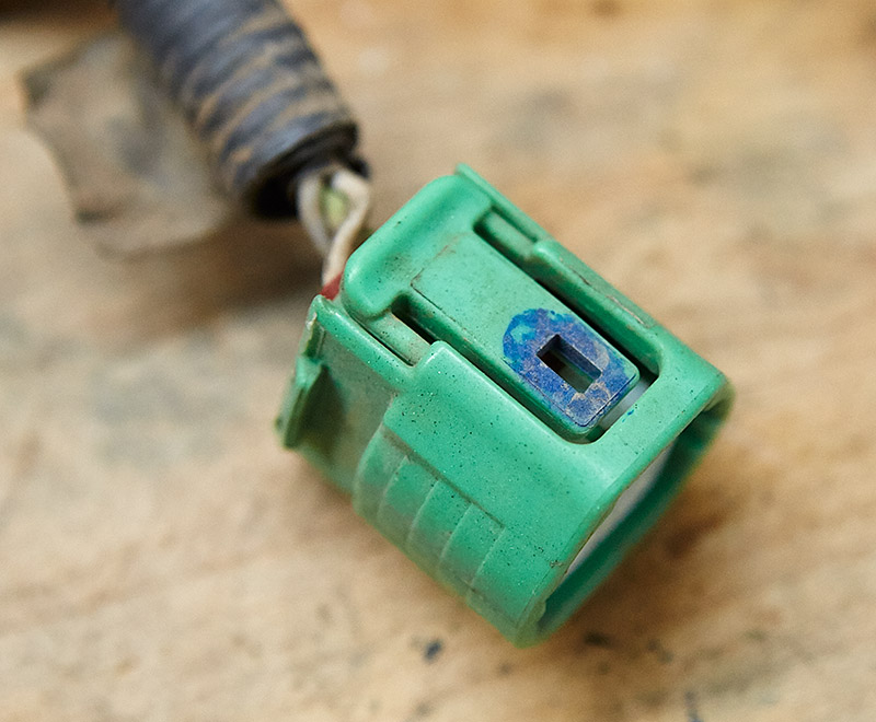
Therefore, I had two choices for making the remote voltage sense wire. The first was to use the existing wire from the salvaged harness, cut it to length, and then add a ring terminal to the end that would attach to the positive busbar. The other option was to buy a new terminal to fit this plug and make a new cable from scratch. Of course, I had to go the hard route and source the terminals. This also allowed me to change my mind if I wanted to somewhere down the road and use the original sense wire. The type of plug is a Sumitomo, Part # 90980–11964, and the terminals are Sumitomo TS / SL Female Terminal 0.5 - 1.25 mm2 ( 20 - 16 AWG ). I ended up buying the terminals from
Ballenger Motorsports. I also had to buy the
wire seals.
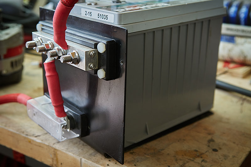
I was almost ready to get down to business and make my new harness. However, I first needed to build a bracket for the ANL fuse holder and Blue Sea 600A positive busbar to be mounted to. Without this, I wouldn't know how long some of the cables needed to be. This is nothing fancy. It's simply 13ga steel that I cut, bent, and painted. The battery holds it in place with the friction of the battery hold-down.
My reasoning behind using busbars instead of routing all cables to the positive battery terminal is simply for cleanliness. I already had several cables going to the battery terminals, and this was only going to get worse with the Big-3 upgrade, my future-planned fuse block, stereo, compressor, etc. Therefore, I went with a positive busbar to keep things nice and clean.
A couple points to make note of:
- I used nylon bolts to secure the busbar to the bracket. I did this to eliminate any risk of a short through the mounting hardware and bracket.
- I used a plastic busbar protector that is not shown in this photo. But you'll see it in the final image of the completed installation.
With the bracket complete, I started wiring things up, but you can't make cables of this size without a heavy-duty crimper. I first asked several motor-heads I know if they had one I could borrow, but no one did. I then briefly contemplated using a crimper at a nearby West Marine, but I honestly felt that that wasn't very practical. I ended up buying a
Quick Cable 4255-001 crimper from Battery Mart. I'm sure you'll agree as you read on.
I justified the cost of the crimper with other future projects in mind and that I can loan it to friends. Furthermore, I've never really hesitated buying tools throughout my life. It definitely makes a job easier, and sometimes it's the only way to do something correclty. But I digress...
My methodology for making each cable was the following steps:
- cut a length of cable slightly long
- crimp a lug to one end
- connect the lug at its termination point(such as the starter)
- route the cable
- cut to length
- strip insulation
- temporarily slip on lug
- mark indicator line across lug and insulation with a Sharpie
- remove cable
- crimp the remaining lug while aligning the Sharpie marks
- install Techflex and heatshrink tubing
- install cable
- use zip-ties to temporarily secure cables together as more were added
I found that it was important to follow this procedure in order to not have excessively long cables that would cause improper fitting. Furthermore, using a Sharpie to align the second lug helped to position it correctly. I could have certainly forced a twist in the cable, but following this process allowed the cable to lay flat and not get in the way of anything else. This was exactly why having a crimper on-sight was vital.
I continued making cables patiently. In fact, this was spread out over a few days around my normal work schedule.
Once I was satisfied with the cables, it was time to protect and restrain the harness. I re-used a lot of components from the salvaged wire harness I purchased, such as the brackets, heat shield, and split-loom. To bind the cables together, I used dry vinyl tape as a base layer with standard electrical tape over that.
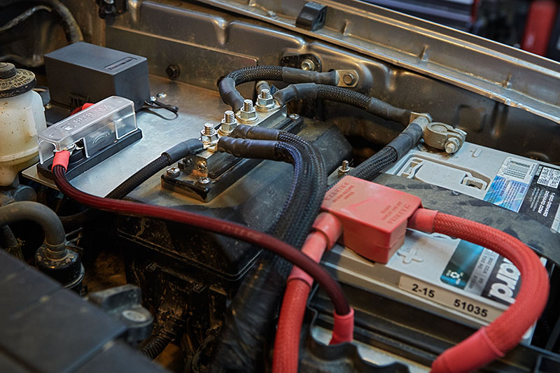
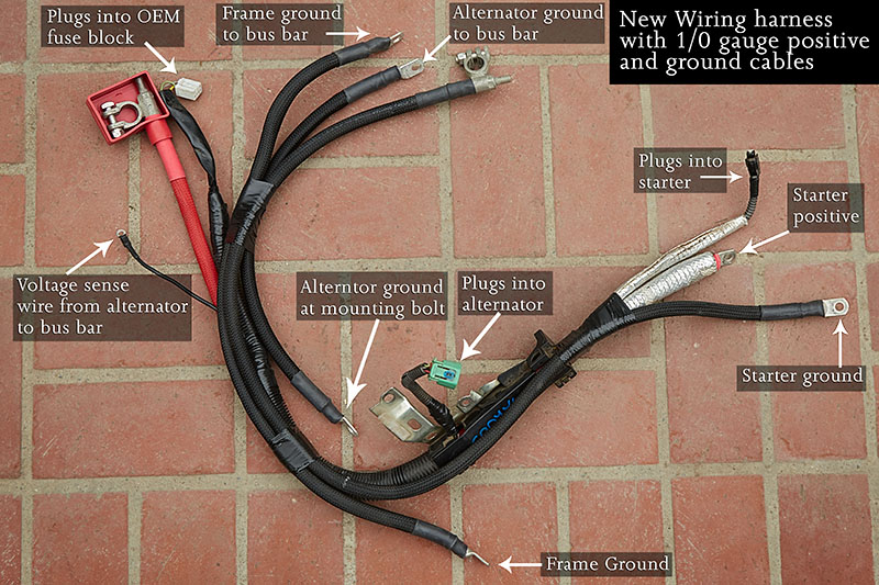
The following picture shows the completed harness. If you compare my harness to the OEM harness, you'll notice one key cable missing, and that's the alternator positive cable. With the distance from the alternator to the ANL fuse holder being so short, I ended up keeping this cable separate from the harness.
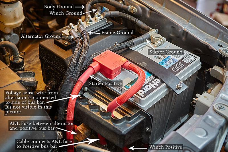
The final step was to install the ground busbar, which I bolted to the lid of the OEM fuse block. I drilled holes through the lid and used black RTV gasket maker around the holes. The following picture shows the completed installation.
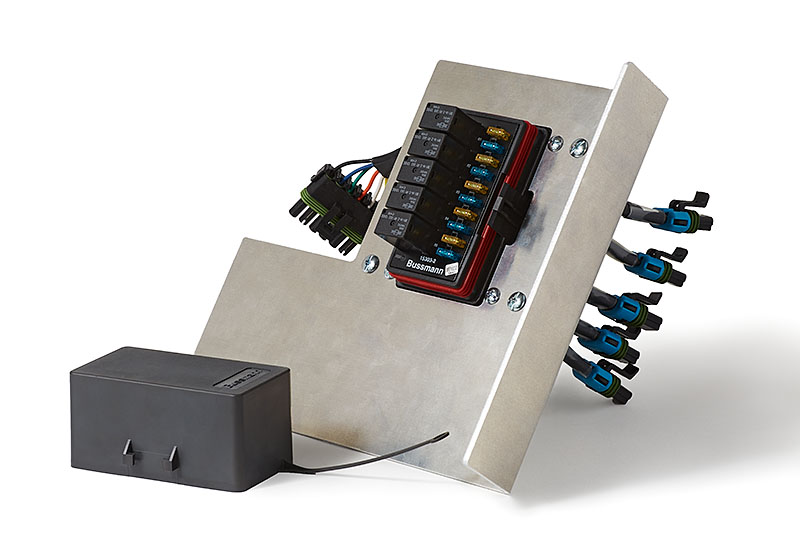
Now that this project is finalized, I'm very happy with the outcome. It took a lot of research, time, patience, and hard work to complete. I'm aware that some people might think that this is a bit overkill, but I approached this project with the mentality of "Do it once". Therefore, this will serve as the foundation for all future electrical needs on my vehicle. The next phase is a Bussmann RTMR fuse/relay block, which I'm currently building.
 :yikes: