Blender, My LX450/FZJ80 + FJ45esk + GM + Land Rover crazy concoction

Metcalf

Expedition Leader
Nothing amazing this weekend, I got sucked into fixing the misses car, which didn't really need fixing. Did you know that having some sound deadening material de-laminate off the door of an Audi and get trapped behind the window sounds JUST like the regulator is broken....


I did get the dash seam welded up completely and sanded flat. It isn't perfect, but I am pretty happy with it! I still need to sand down the high points on the other seam, but those are going to be covered with a plate that will tie the A-pillar tube into the dash/cowl structure for a little extra insurance...


Something like that I hope. I should be able to slot the intersection where the tube touches that plate and weld it from the back side before installation. That should make it look very clean. The perimeter of that plate will be welded to the sheetmetal of the dash.


I also made the templates for the structure that will connect the A-pillar to the floor. This ties in directly to the body mount system and to the frame through the rocker outrigger. I also have to go in and weld all the seams under that new structure where I pie cut the floor and door.

Hopefully I will be able to actually bend a tube this week!
 

vwhammer

Adventurer
I know it was a while back and perhaps I missed it but what precisely was involved with changing the LT230 flanges to bolt up the toyota driveshafts?

I noticed you used some 9" pinion flanges with multiple bolt patterns but what else needed done to make it work?

I also need to mate the land cruiser shafts to an LT230 case.
I suppose I could just get the flanges and go from there but you mentioned some possibly tricky work needed for the seal

Just Curious and thought I might take advantage of someone else's legwork to save some time
Not trying to take advantage of your work... Well, wait I guess I am.
 

Metcalf

Expedition Leader
I know it was a while back and perhaps I missed it but what precisely was involved with changing the LT230 flanges to bolt up the toyota driveshafts?

I noticed you used some 9" pinion flanges with multiple bolt patterns but what else needed done to make it work?

I also need to mate the land cruiser shafts to an LT230 case.
I suppose I could just get the flanges and go from there but you mentioned some possibly tricky work needed for the seal

Just Curious and thought I might take advantage of someone else's legwork to save some time
Not trying to take advantage of your work... Well, wait I guess I am.

There isn't a perfect option, but I think the 9" trail gear flange is probably the closest option.

You basically have to cut/face off the counter bore section where it goes into the t-case to get a decent amount of spline engagement.
To make it ideal, it would help to make the counterbore on the front where the retaining nut ( for the output shaft ) a bit deeper.

The seal can be done a few different ways. The factory OD of the 9" flange is very close to 46mm. The factory LT230 flange is 45mm. I found seals to go either way. In the end I decided I will turn down to the OD of the flange for a 45mm factory seal. I have thought about talking with Trail Gear about making me a correct set of flanges, but I will likely just modify the ones I have.

You will need to delete the e-brake off the back of the LT230 also.

I hope that helps. I should have some more details on that stuff as I button things later in the build.
 

Metcalf

Expedition Leader
Just a little bit tonight. Turning cardboard to metal always takes longer than I would like....


That one panel took the majority of the evening season to make and fit. It has at least 2 bends plus a step-up flange on the outside rear to match the blister in the floor. There was a lot of filing and fitting also. Overall I can't complain though, I didn't scrap the part and got all the features to work together on the 1st try.

A few tricks for the night....


I like using magnets for holding templates down instead of tape these days. Even if the edges are not completely down, the template won't move around if the magnets are strong enough. I just press the edges down and use a sharpie to trace the edges. This also works great if you have to mark holes and stuff. Use more magnets rather than less.


I am also going to try something to help keep the position of the A-pillar on the pad consistent for the cope/trim. I cut a short section of 1.25" tube which will fit inside the 1.5"x.120 wall tubing I am using. The same could be done for other sides. You just tack the INSIDE of the little spud tube in place once you know the location where you need the tube to hit the pad. Now, every time you take that tube in and out during the fitting process, it will be in the same spot. I just hate it when things are trying to move around in too many places at once.

I will hopefully be pulling the entire A-pillar sub assembly, including the floor pad, out for welding after fitting and tack welding. It might take a little tap-tap with a dead blow to get everything in and out however. We will see.

And....


My tubing bender works. I had to 'waste' a bit of tubing to figure out where the Start Of Bend is on the die along with about how much spring back this material has. I think spring back is about 3-4 degrees.

Tomorrow I should be able to bend up the A-pillar and start fitting it. Yipee, but man this stuff seems to go slow sometimes.
 

Metcalf

Expedition Leader
One part at a time....


I was able to get the A-pillar tube bent up and fitted to the body and existing structure. It took a little time and patience to get the tube joint like I wanted. This tube 'falls off' the inside of the horizontal door bar of the halo by about 1/2". This isn't really anything fancy, but rather just a little bit of thinking ahead that came together...


Here is the position of the A-pillar compared to the dash and cowl support. I think I lost less than 1/4" of space to the inside. I tucked the tube as close to the forward outside corner as I could. You can see how close the tube is to the corner of the dash that I had previously moved inboard.


Close-up of how the A-pillar fits with the relocated dash corner....


This is how much the tube hangs off the inside of the door bar tube of the halo. This has been left long so that it can be trimmed to fit the future spreader bar at the top of the windshield. That will the odd rolled and bent part I talked about a few posts back.


I cheated and used Solidworks to make and print a template for the cope I needed. It was actually pretty close, but I did leave things about 1/8" long and trimmed it to fit....slowly......mostly with just a file.


If you haven't guessed. I make a lot of stuff. Here was my improvised 'Plane of Bend' clamp. I had to sneak in a little 1-2 degree bend in plane with the major bend to help this tube fit close to the dash. This little device helped me keep the tube perfectly in plane between bends.

Now to repeat everything I did on the drivers side. I probably won't post much along the way since all the tech is the same......cutting the dash, floor plate, fitting the a-pillar, etc. I hope it doesn't take too long, I really want to make that spreader tube which will need to be rolled and welded. That should be a nice challenge along with the last complex tube in the cage for a bit....
 

Metcalf

Expedition Leader
Small victories....


The drivers side is pretty much like the other, but there are a few small differences. For some reason Toyota thought extended a rib on the floor right into where I needed to put the A-pillar floor pad. On the passenger side there is no rib in this location. I wanted the parts to match, and I didn't want to have to cut out a section of the floor. I started with the saved template from the other side, I just reversed all the bends and flipped it over. Coming up with a way to press that rib into the bracket was interesting....


Scrap metal press brake tool for the win. It wasn't perfect, but it worked rather well for a one off tool with a minimal time investment. Sometimes it is not the tools you have, but the ones you make along the way....


I also sectioned and relocated the dash corner on the drivers side. This side was a bit easier because I didn't have to work around or inside the glove box. It was much easier to get access with the hammer and dolly when doing the seam work.

Now onto the A-pillar tube and then hopefully the fancy rolled windshield spreader bar this weekend. Once all that it fitted I also have to make all the gussets, weld them in, weld the plates to the floor/dash, etc. Lots to do, but it will feel SO good to have a complete cage! Once that is done I can move onto some different stuff like making the rear sheetmetal. I also need to think about making the tunnel soon. I also have an idea for a new press brake tool that I am thinking about constructing....
 

Metcalf

Expedition Leader
Weekend update, 'who's dumb idea was this'.....


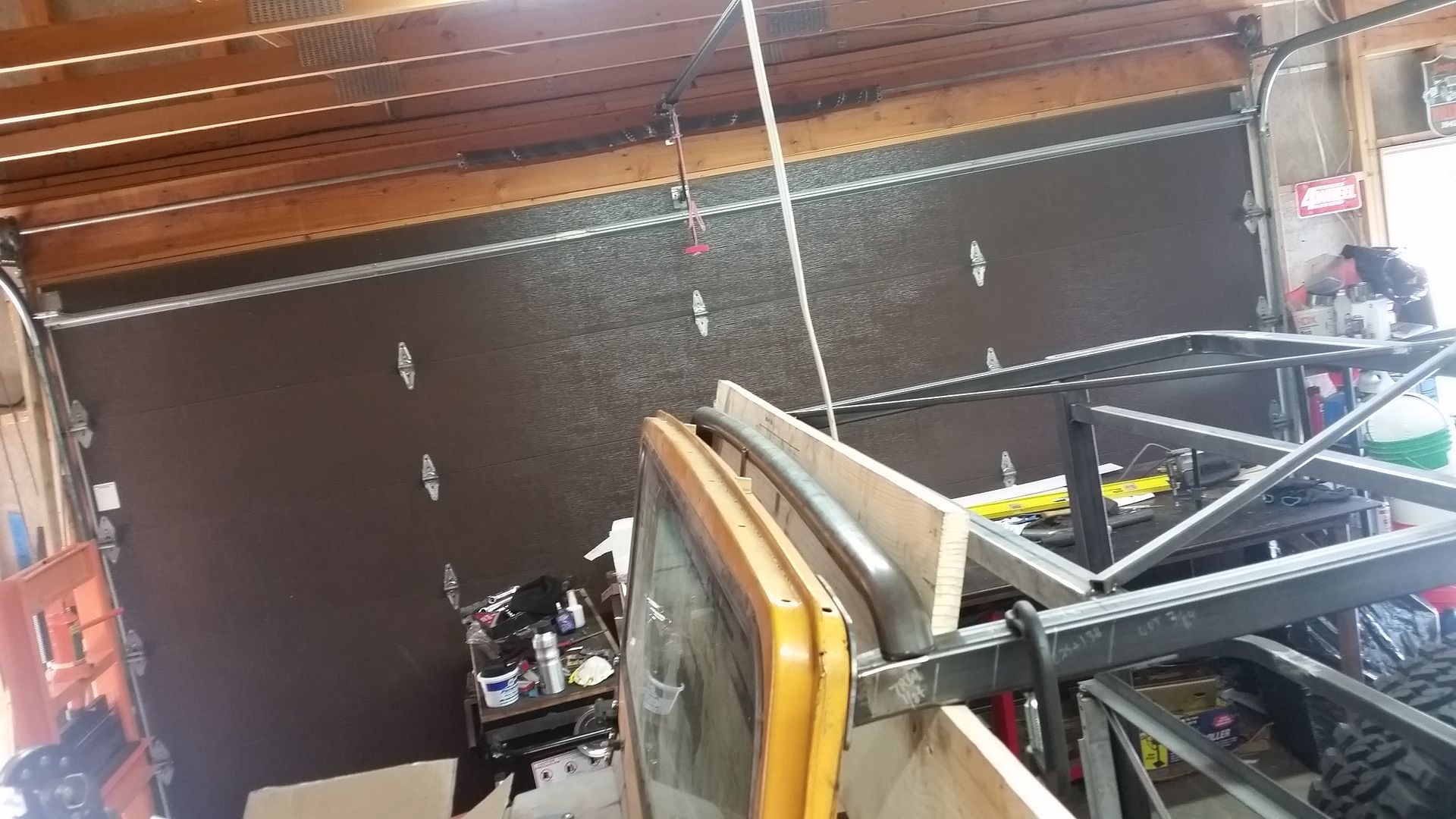
This is where I ended up after a few more days of playing with tube. One of my pet peeves with cages is that there is typically a lot of wasted space, specifically over the top of the spreaders. I am trying to combine a lot of different features with my 'cage' and that makes things a more challenging than I want to admit sometimes. I try and stay ahead of the curve and plan ahead....but dang this one tube kicked by butt all day long.

The top of the FJ40 windshield has a gentle curve that I wanted the windshield spreader bar to follow. Since that radius is so large, I needed to roll that section of the tube, but also give myself enough straight at the ends to be able to add a 45 degree drawn bend to each end AFTER the rolling process. In order to facilitate that I had to leave a 4" long straight section between the rolled bend and the start of the drawn bend. That 4" is the minimum distance on my bender from the start of bend to the retaining strap on my Pro-Tools 105, 1.5x4.5CLR die. It also just happens to be just about the exact distance between the rollers on a Harbor Freight tube roller.

I guess I need to take a step back for a minute to explain the setup...


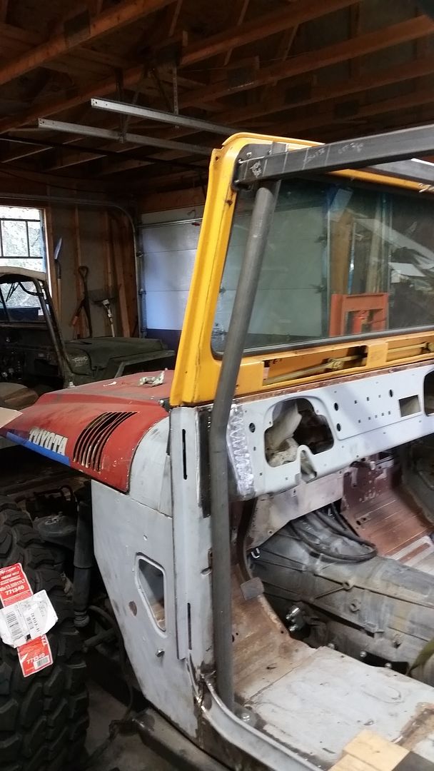
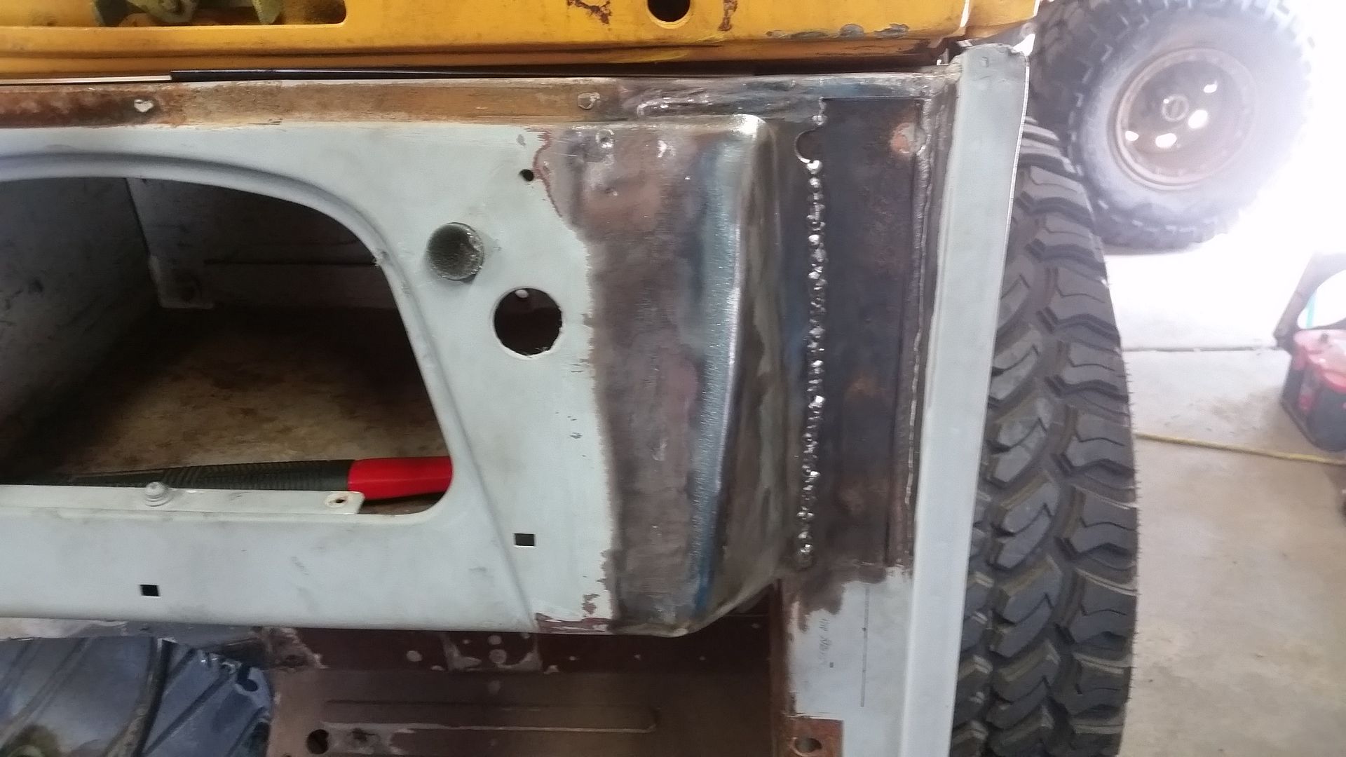
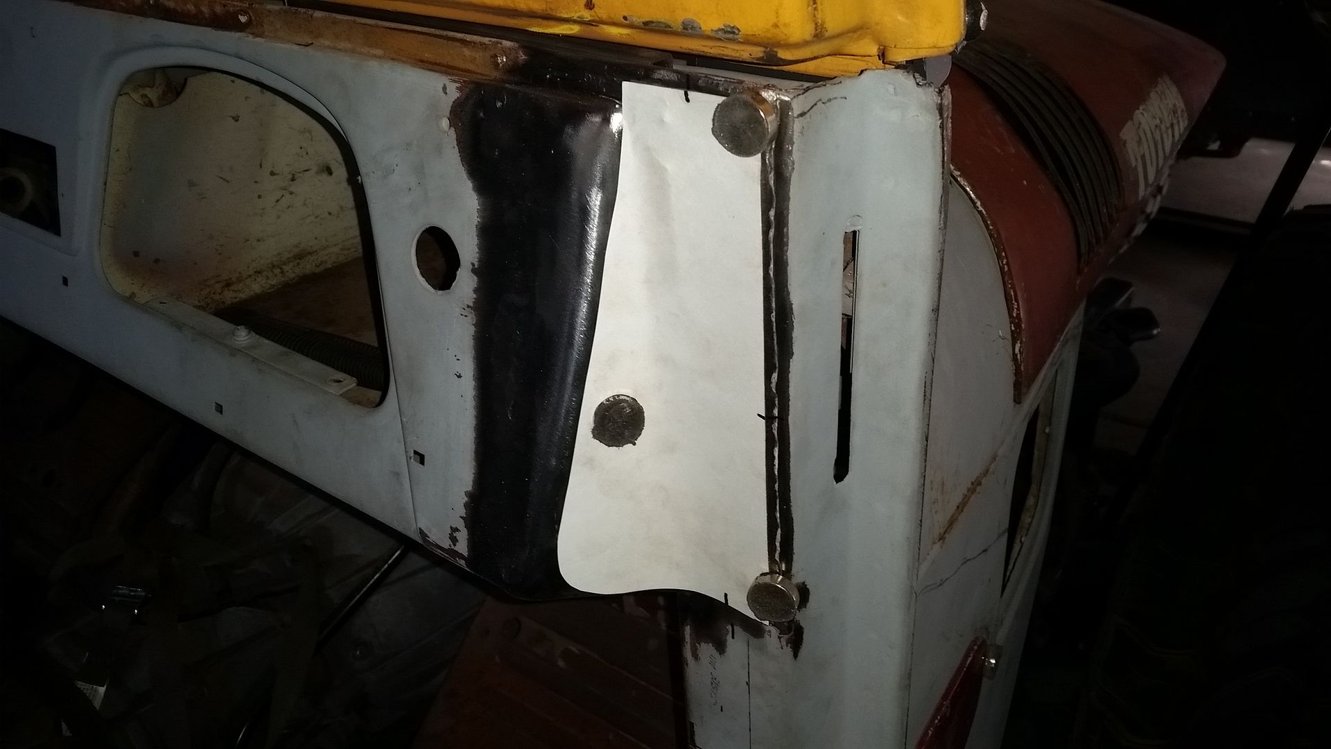
I needed to finish off the A-pillar down tube for the drivers side. That wasn't a big deal. I actually got pretty lucky and it went much quicker than the 1st one on the passenger side.


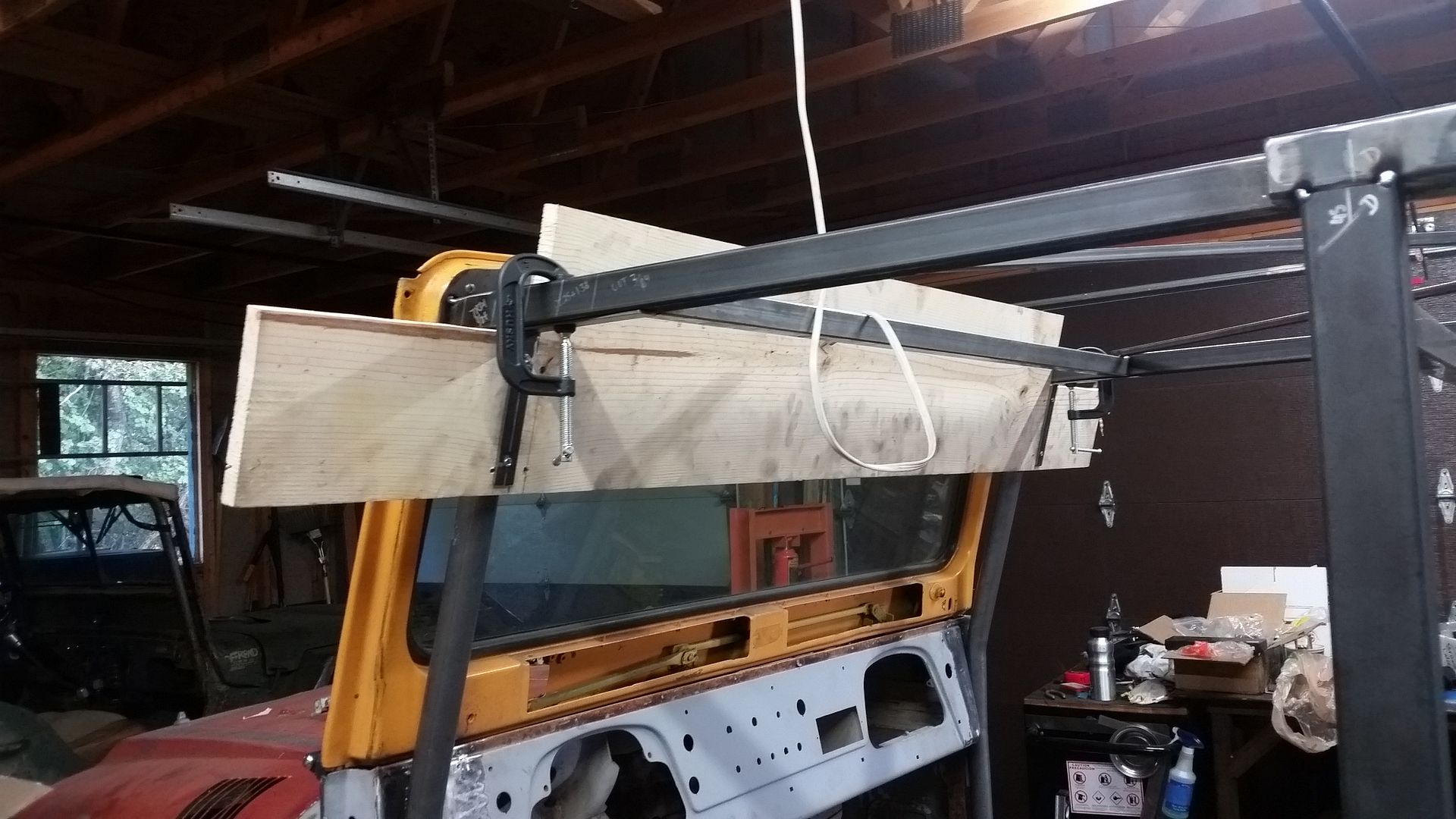
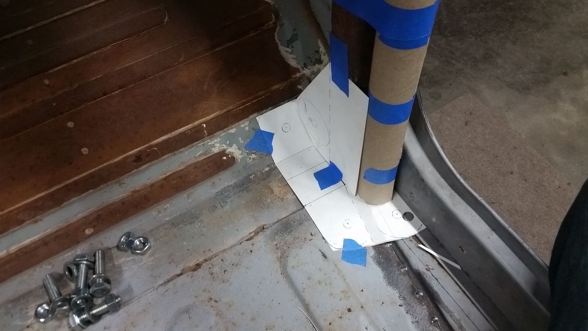
Once I had both A-pillars done, I could build a 'plane of bend' jig that would allow me to trim the windshield spreader bar without the A-pillar tubes in place in a known reference position. I also wanted the windshield spreader bar bend plane to be leaned back at the same angle as the windshield an A-pillar. There was a lot to keep track of in this, so I figured it was worth the investment in time to make this little jig. When I no longer need it, the wood will be donated to the fire gods in my wood stove....


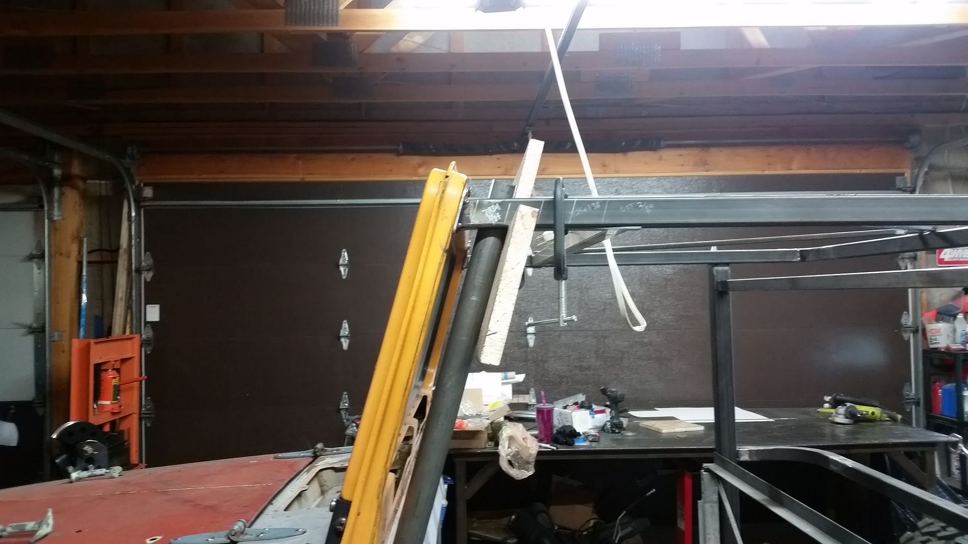
Here is another quick shot from the side....


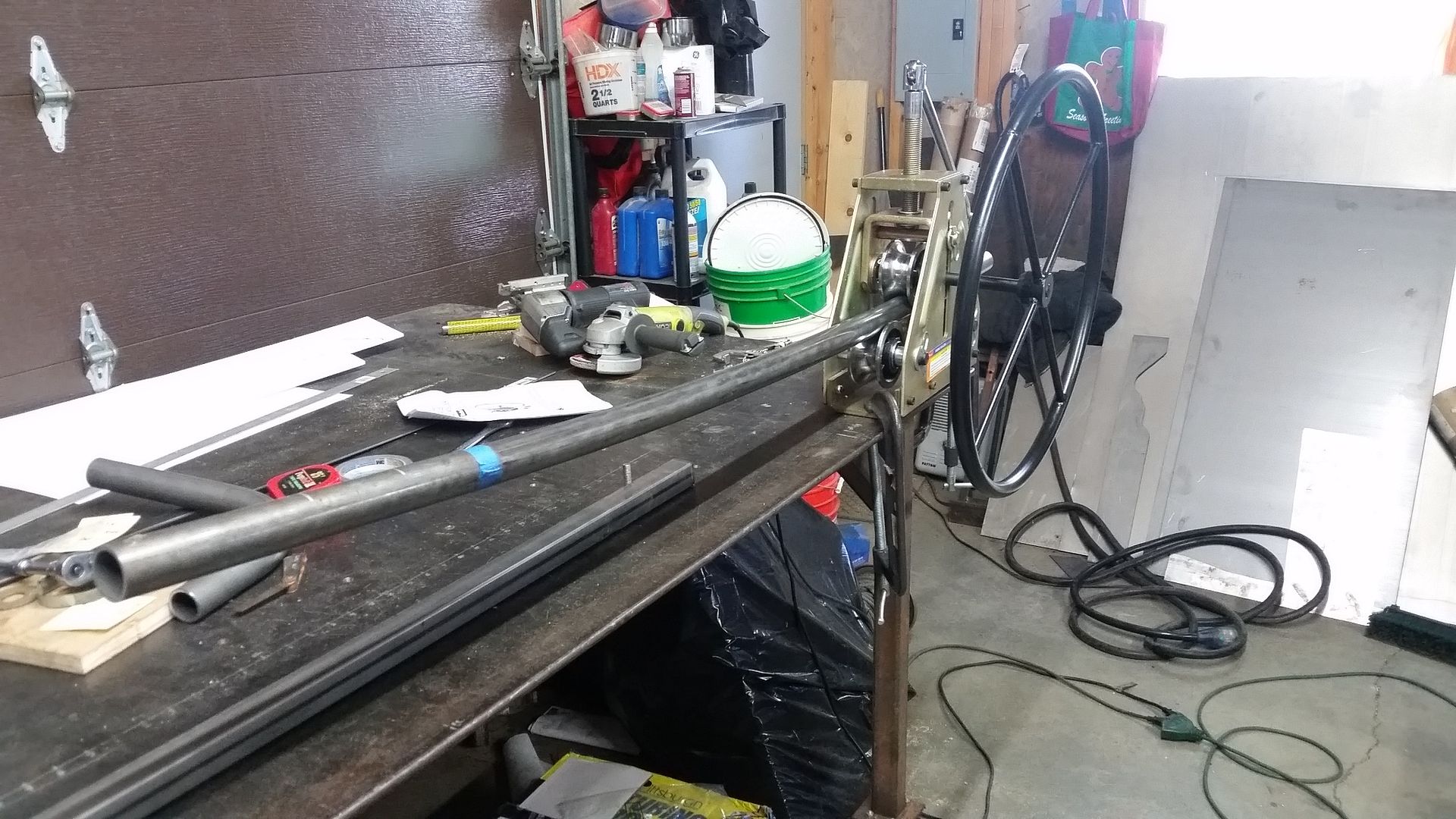
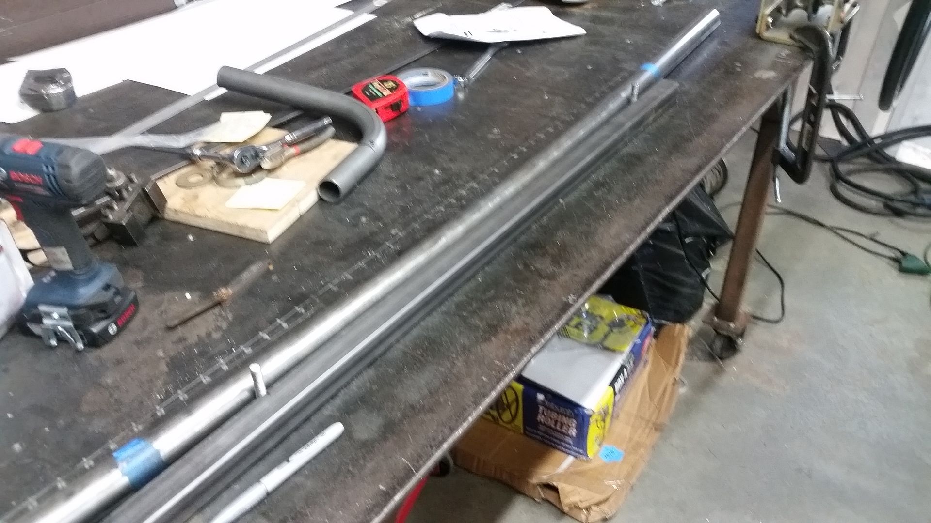
Well, lets play with some tubing! I picked up a HF tubing roller a few weeks back on sale with a coupon. It actually worked way better than I thought it would for the money. It does take a decent amount of force on the feed screw, I ended up using a 1/2" breaker bar and going about 1/8-1/4 of a turn per pass. A single wrap of masking take made a good reference point on where to stop and start. I needed to start and stop in the same spot and have a known length of rolled tubing. I believe that the end of the roll has to go to the centerline of the middle roller. The tail of the roll remains straight from that point out I believe.


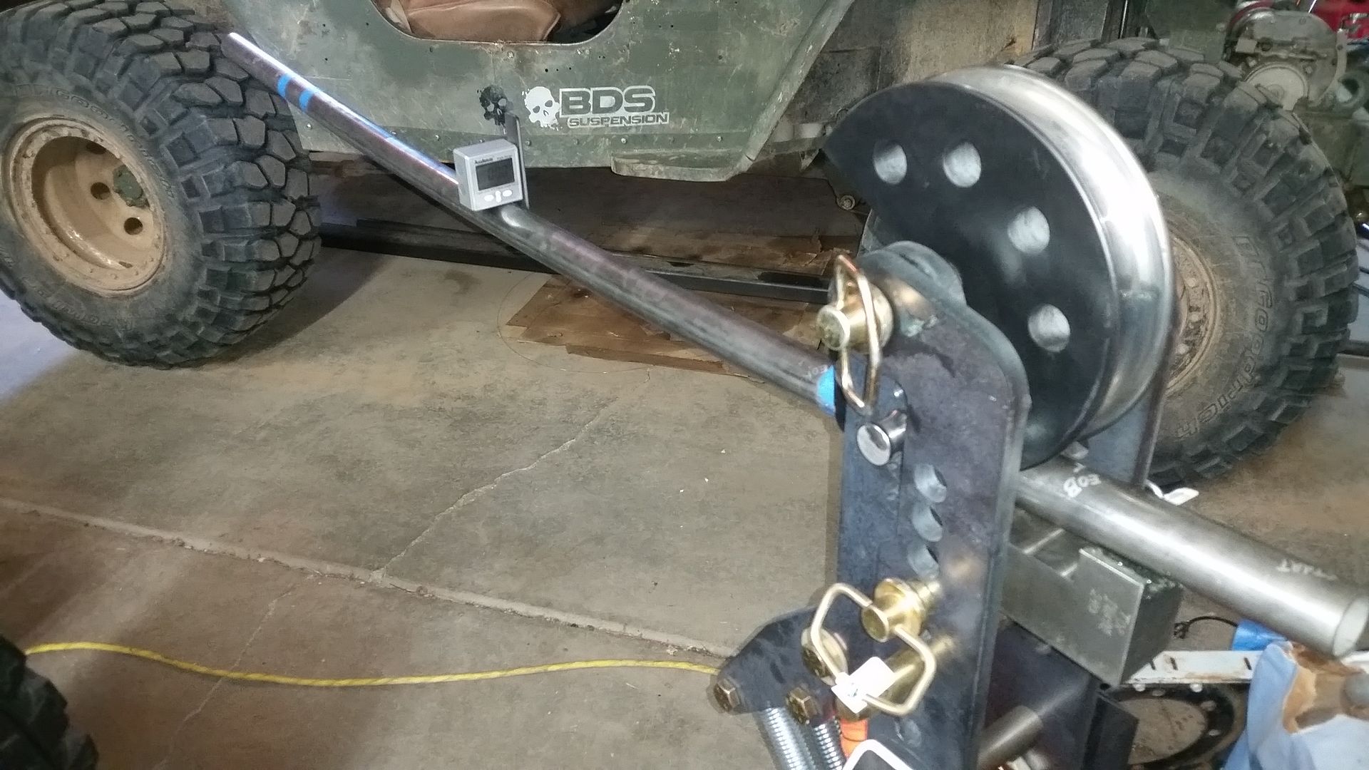
I rigged up a quick jig so I could check the bend radius. For this bend that was .382" of deflection over a 30" span. My welding table just happen to have a 6" grid pattern, so 5 holes is 30" ( or close enough!). The table is tapped for 3/8" threads too. By inserting a two sections of all thread in the table and using a straight piece of tube, I was able to make a crude radius gauge. It was fairly easy to pull the tube out and test the radius in this device so that I could sneak up on the shallow rolled radius I needed to match the windshield.


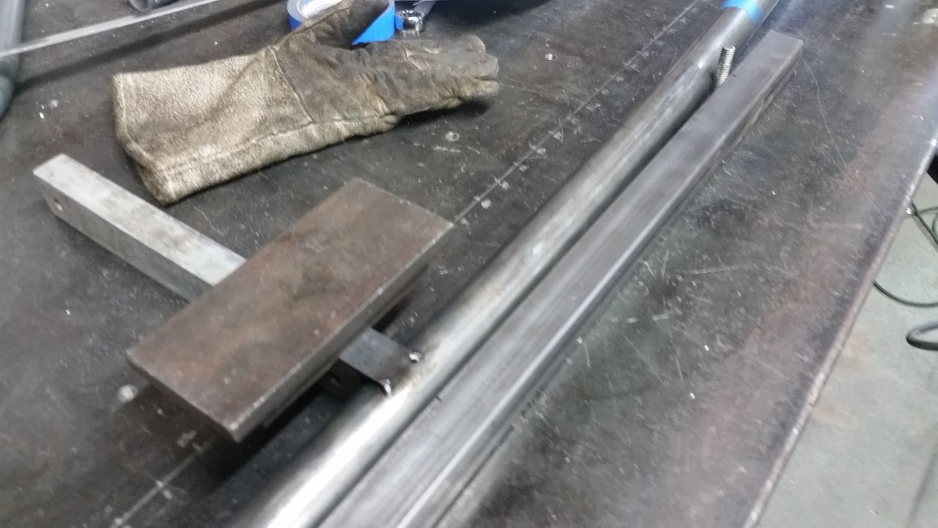
Since I needed to add 45 degree bends onto each end of tube, I needed to have a 'plane of bend' reference to set it up in the tube bender. I did this by welding on a small 'flag' of bar stock that was parallel to the bend plane. Since the tubing is 1.5" diameter I was able to align this 'flag' by setting it on a section of waste rectangular/square tube that was also 1.5" high. I used two good tack welds and made sure to check the alignment after welding since it will pull a little bit. It was easy to check the alignment with the little scrap section of tubing.


This is how that works when you stick the tubing in the bender. This lets you keep all the bends in alignment. It ended up working out really well overall. I was able to keep all 3 bends....1 rolled large radius, and two 45 bends all in plane while having to move between all 3 different setups.


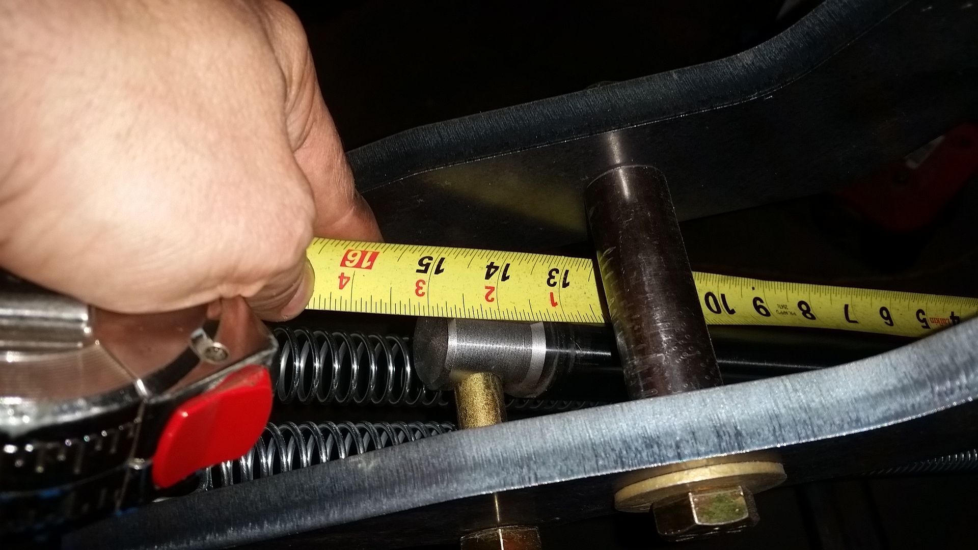
Last tip. On my vertical style bender, I found it very easy to measure the overall ram extension as a bend angle reference. I did a test bend and was able to use that number on the two final bends. It worked sweet, was very accurate, and gave very repeatable bends. Not that it helps me much, but now I know that a 45 degree bend is 14 13/16" of ram extension on this die with 1.5x0.120 wall DOM tubing including springback. I didn't have a lot of level surfaces on the rolled tube or extra tail on the end to use an angle finder. I used the absolute minimum amount of wasted tail on the bends to keep down tube waste. On my machine that is 6" of straight tube in the following die minimum once you figure in spring back. The end of the tube actually sucks up onto the flat of the following die.

I think that is all for now. I still have a lot of work that needs to be done on the cage but all the big parts are made. The top of the A-pillar tubes need a slight trim to match the windshield spreader. I need to make and fit the gussets. Then I will finally be able to take it apart and weld everything...I think....unless I forgot something.......
 

Metcalf

Expedition Leader
Just a little bit tonight....


I was able to get the A-pillar uprights trimmed to fit the windshield spreader bar along with getting the spreader tacked into place tonight. It took a bit of in and out with all the different parts, but it worked out in the end.


This is how the offset A-pillar upright was coped around the door bar and into the windshield spreader. Overall it was kinda a pain, but just takes a little time.


Before I pulled the flag off, I gave it all a final check. The goal was 16 degrees to keep everything in plane with everything else. I can't complain about how it came out.

The uprights are tacked to the floor places also. I will have to pull the windshield off I think and lift up the halo slightly to get them out cleanly. With them pulled I can weld the full joint on the floor plate where he tube is tucked into the corner. Fun Fun. It will be SO nice to get this back together for the final time and fully welded. Then I can pull the temp bracing out and start on filling in the rear portion of the cab!
 

Metcalf

Expedition Leader
Small bit of win tonight...


The A-pillar upright, once tack welded to the floor plate, and with the windshield bar tacked in place actually popped out of place! I didn't have to pull the halo off the windshield or anything! Win. I had imagined that it might be possible. but once I had everything tacked in place I had my doubts. Everything is less than about 1/8" clearance to the dash, the dash corner, the door brace, etc. Little wins.


I fully welded the windshield bar to the halo after I pulled the A-pillar uprights out after they where tack welded to the floor plates. Once they where removed from the body I was able to complete the welds at the floor plates. After those welds where finished I had to re-trim the uprights slightly to clear the welds on the windshield spreader. It's like chess....


Here is the most expensive primer ever. You are suppose to be able to weld through it......we will see how that turns out. I wanted a little protection on between mating surfaces that basically have no chance of getting hit with paint later.

Tomorrow I should be able to start welding in the uprights to the body. Yippe. I need to make a few gussets still. The floor plates will get a pretty big gusset to spread out the load from the upright over the entire floor plate instead of just the outside corner. That is probably gonna need at least one dimple for flair points. I am also going to tie the upright into the old dash seam on the cowl. That should provide a little more structure for the upright near the bend.

Once all that is done, it will be time to move onto something new.....so many choices.....so much to do.
 

Metcalf

Expedition Leader
Back to making brackets again....and welding.....


I was able to put the A-pillar uprights back in, snugged the bolts back up, and started welding the plates to the floor. This cage is designed to be an integral part of the truck and body. Welding to the old floor sheetmetal was fun. I also got the uprights heavily tacked to the halo.

I still have some more welding to do at the front/top of the floor plate, but I was a little burned out on welding....so I started making the 1st of the tie in brackets. These plates will spread the load out from the A-pillar tube down across a larger area of the floor and to more of the body mount. The A-pillar is so far outboard in the corner of the door that I figured it would be a good idea. That brace will be welded in after I finish the pad welding.

I also want to make another tie in plate/gusset/brace at the dash to the outside corner where the original location of the dash flange.

Tip of the day....


If you need to make a mirror of something, sometimes it is easier to make two at once and then cut them down the centerline. With the scallops it was easier to just cut holes 1st, then just slice up the middle to make the twin parts.


I am still digging the magnets for holding down templates. These are strong enough that stuff doesn't move around when using poster board. It is hard to tell, but if you pre-center punch the poster board template for the hole locations, you can use the template either direction to allow you to mirror the part to combine features.
 

Metcalf

Expedition Leader
I finally got to sit in it!


The last few days of work consisted of getting the cage welded into place in the body so that I could remove all the temporary bracing finally! All in all it went pretty smooth, welding to old sheetmetal generally still sucks no matter how well you clean things. It did feel amazing to be able to sit in the body for the 1st time really. I had always had a bar here or there in the way. This was the first time I got a good feel for how things are with the 'pinched' body.

Since I took all the taper out of the doors, this body is only about 56" wide now with 52" between the b-pillars. That is basically about 3" narrower than your typical CJ/YJ/TJ tub and even an inch narrower than an old flat fender tub!

Overall it feels like a 'tall' version of a toyota extra-cab truck to me. The seat will be able to be up off the floor a bit more. The top profile is going to be slightly shorter than stock, but the seats should still be up off the floor a bit. I think the seats will be somewhere between a toyota mini=truck and something like a jeep. There seems to be plenty of length in the cab. I only extended the cabin about 3" longer than a stock FJ45. That does seem to be plenty of room for what I want. I have short legs and a long torso so I generally drive with the seat forward a bit more than most. There should be a few extra inches of room for rearward seat travel for those who need it.

I would like to mount the seats on sliders. That should make it a little easier for other people to drive it when needed. If I can come up with a way to make it fairly easy to adjust the vertical seat height and bottom cushion angle I would like to be able to do that also. It doesn't have to be an on the fly thing, but more like change a few bolts thing. My hope is that the b-pillar spreader on the floor will provide the majority of the structure for the seats.

It did feel really good to sit in it!

Now I need to clean up the shop and get into sheetmetal mode....rear floor, rear body panels, the tunnel, etc.

Some misc pics from finishing up the 'cage' stuff....


Metcalf

Expedition Leader
Time to hit sheetmetal with a hammer a few thousand times...


I need to make the rear floor panels. These panels need to have a flange on the outside where they will join to the rear cabin panels. I elected to make an MDF hammer form for these panels. They needed a 5.25" corner radius to match the belt line spreader bar tube. With 16 gauge cold roll material the MDF won't last long, but it will last for one part per side (edge).


This picture has a lot going on. You want two identical layers of MDF to clamp the panel. On this panel I only needed the flange to be on 'two' sides and wrap around the corner radius. I could have the pins and a few screws off the edge of the panel easy enough. Using a block of material that is the exact flange measurement you need. I used the handle of my 'bendy stick' which was 3/4" square stock. You can use it to mark an outside radius. It is also handy for aligning the straight sections as a measurement tool and a little hammer taping. I had 3 wood screws to clamp things once it was in the right place.


Then I clamped the entire assembly to the table corner with lots of big C-clamps. You have to move the clamps around to have access to the entire flange. You want to work the flange down as evenly as possible. You DO NOT want to work it all the way down at once. Go slow. Use a body hammer with light hits. You can also use a large crescent wrench to get the bend started.


After LOTS of hammer hitting you will end up with this. Note how the straight sections ended up nice and smooth but the outside corner bunches. This is because outside corners need to shrink. Inside corners stretch. If you planning out flanges, make sure to give yourself a little extra flange on inside corners and don't worry about it too much on outside corners. The flange will grow in length if the curve requires shrinking. Clear as mud?


Here is a close up of what the panel looks like after the hammer form. With a larger radius and/or a strong enough hammer form material, you can continue to hit the high spots and the metal will start to shrink. MDF is not strong enough for this, so we have to clean it up after it is removed. As long as the radius is well defined it isn't a huge deal.


This is what you end up with if you hit the high spots enough times on a somewhat matching radius die. The die doesn't have to match exactly, but closer is better. You basically just tap the high spots over and over till they shrink and lay flat. The flange will grow in length as you do this.


If you want to tune it up even more you can do a few passes through a shrinker. This is the HF unit. I picked up their shrinker/stretcher set on sale a bit back. This radius is a little tight and not exactly what these are intended to do. It did help tune up the flange and make the panel level on top again.

I will make the mirror tomorrow in the same form, but the opposite direction. I cut both blanks already so it should go pretty quick. Once that is done I will trim them to make an assembly and weld the centerline seam. I am also thinking about trying to make a quick press tool to replicate the 'bumps' in the front floor panels to keep the panel quiet...and make the parts look more oem.
 

Metcalf

Expedition Leader
Still working on the rear floor panel....


Side B (D?) went the same as side one. I was able to use the same hammer form for the opposite side, just bending in the opposite direction. This gave me a fresh corner also which gave a very similar bend to the 1st, without having it be any softer. The process was done the same...crescent to start, lots of hammering in the form, then more hammering over a round dolly to eliminate the tucks, a few passes on the shrinker, and then some light hammer/dolly work to clean it all up...

Don't mind that extra TIG weld seam either. I TOTALLY meant to do that. I didn't make the panels a bit shorter than I needed. I needed the sheetmetal TIG practice anyways....


As a small side bonus, it will center the twin seams since that is the only panel I trimmed.

This is how I set up the panels to get a rough measurement for where to trim. I gave it about 1/8" extra and trimmed everything to fit carefully. That will leave me with a nice flush butt seam to tig weld.


Here it is all trimmed to fit. I used a long straight section of bar stock to align the rear flanges. I was careful to trim the length down carefully to set the overall panel width.

I will weld it up tomorrow.

Then I might need to figure out how to press something into the panel to stiffen it up a bit. Something like the bumps in the OE sections of the floor perhaps.....
 

Forum statistics

Threads
185,886
Messages
2,879,179
Members
225,450
Latest member
Rinzlerz
Top