Blender, My LX450/FZJ80 + FJ45esk + GM + Land Rover crazy concoction

justcuz

Explorer
Maybe, since I am stretching the cabin area from 'stock' FJ45 length a little bit, things become a little more complicated.

If I did start with a stock roof panel I would have to cut it into a lot of pieces and hope it all came back together somehow. Once you pie cut something the rear lines change, changing lengths makes you have to add/subtract crowned material, then you have to blend it all together. At some point, starting from scratch will be easier....I am not 100% sure where that point is.

Making the top panel is a personal challenge to push my skills. I really want to make that panel out of slightly thicker aluminum material for some added structure in case the vehicle where to roll in soft material. I also want to try to make it in one piece to eliminate having to finish a bunch of seams out for paint. Making the female buck will be the hardest part. Once I have the buck, I think forming the material will actually be pretty easy with a 'flow florming' process. Making an accurate, and symmetric, female buck with about 3" of depth will be a challenge. I am tossing around a few ideas on how to make that, it is still a ways off so I have time to ponder. I really don't even have to do that till after the vehicle is running for the most part. The top will be an add-on 'modular' feature to the vehicle.

Gotcha on the pie cut, my thought was it would be small enough to avoid a ton of puzzle piecing.
I hope you can achieve the top construction you are explaining.
Seems like it would require a lot of force to make the heavier aluminum fit the female mold, or I am imagining aluminum heavier than you intend to use.
Have you given any thought to making a mold and laying up the top out of fiberglass? Not as challenging, but the mold could be kept for remanufacturing replacements, same as the female one for the aluminum top.
Have not been back to Pirate since the e-mail, log in disaster, do you have more info over there?
 
Last edited:

Metcalf

Expedition Leader
Gotcha on the pie cut, my thought was it would be small enough to avoid a ton of puzzle piecing.
I hope you can achieve the top construction you are explaining.
Seems like it would require a lot of force to make the heavier aluminum fit the female mold, or I am imagining aluminum heavier than you intend to use.
Have not been back to Pirate since the e-mail, log in disaster, do you have more info over there?

Nothing new on pirate, I try and keep both these threads equally updated.

I'd like to use aluminum that was about .090-.120 thick. If I can get T0 material, and/or anneal it, the forming shouldn't be too bad. I will probably just use some 5000 series marine grate stuff.

The depth to panel size ratio is actually pretty good compared to most parts people make using the 'flow forming' process. That process is basically displacing material with a soft hammer into a slightly less soft female mold. You could do it with the right manual hammer, but I will likely speed up the process by using a 4x rivet gun to speed the process up a bit since the panel is so large. The more hammer strikes the smoother the metal finish.

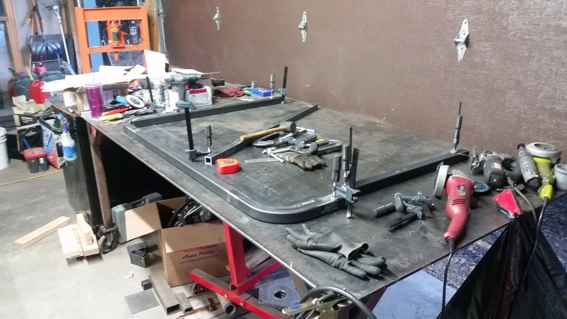
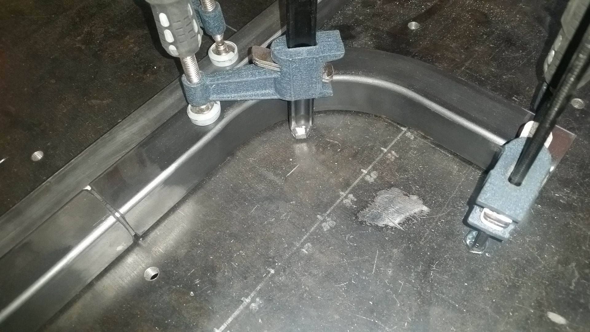
The female mold is the hard part. Basically I need to carve a symmetric complex curved pocket into a block of wood about 60x48x6 inches big.

I might have to resort to something like a 3D router table, but I would rather figure out a way to do this in my garage with more basic tools and a little more time. We will see what I come up with, this is still months away.
 

Metcalf

Expedition Leader
I need a faster metal printer button....


I can't believe that took over 3 weeks, I swear it only took about an hour to model that in the computer! I did take a week of vacation and nursed an L5 back injury for about another week.

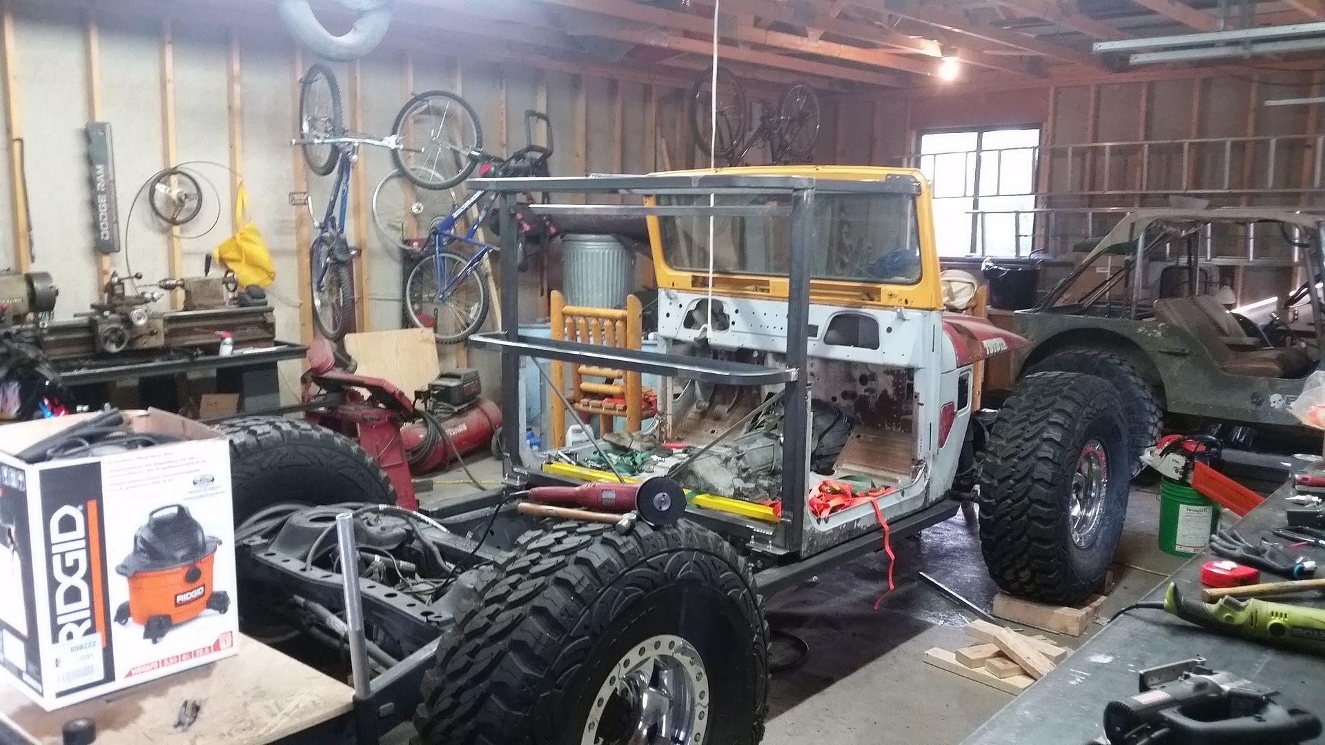
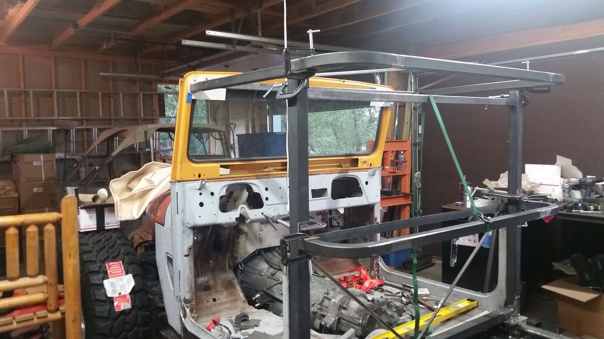
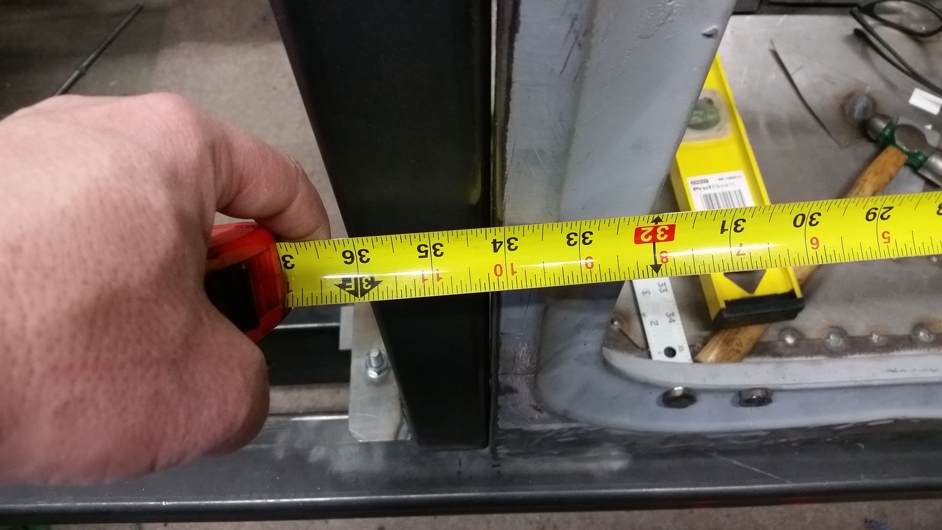
I re-learned a lot about how much fun it is to work with the remains of a stock body. Somewhere in the middle of building this body/cage structure I discovered that one of the door openings was 1/2" longer than the other. That had carried over through the construction of the B-pillar with the body mount and rocker system. I decided that I need to square the body back up during the cage construction prior to moving onto the bed construction. I would be nice if the bed could be square and all that.

Overall I had to do a lot of head scratching on how to move things to get the best overall fit. I generally have everything less than 1/8" square and 0.1 degree to level. That seems to be about as good as I can do with so many parts that can move. The overall body length is now square to the chassis by 1/8" now also. I ended up having to stretch one side the 1/2" to get things back to normal.

I ended up raising the waist line of the chassis about 2.5" from stock. That will allow me to have the rear window panels be the same height as the storage area in the bottom part of the body! That means I will be able to have the rear body panel be removable/replaceable AND store INSIDE the body when not in use! That was a huge design goal for me. I ended up not having to raise the waist line THAT much really to make it possible. I am very happy about that.

The top of the 'halo', where the roof panel will mount, is about 1" lower than stock. I did this to help even up the rear panel/storage difference along with make the vehicle look shorter. I also slightly reduced the overall height of the doors, but I am making those from scratch anyways.I offset the door bars on the halo so I can make angled door surrounds like the rest of the door frame.

I also am planning to reduce the overall crown in the roof panel to JUST match the shape of the windshield frame. This will help keep the overall height of the vehicle down. The seats will likely have to be slightly lower to make up for all this, but the visibility should still be good with the stock height windshield frame.

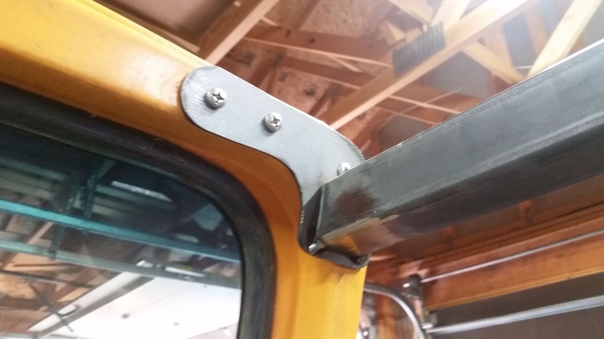
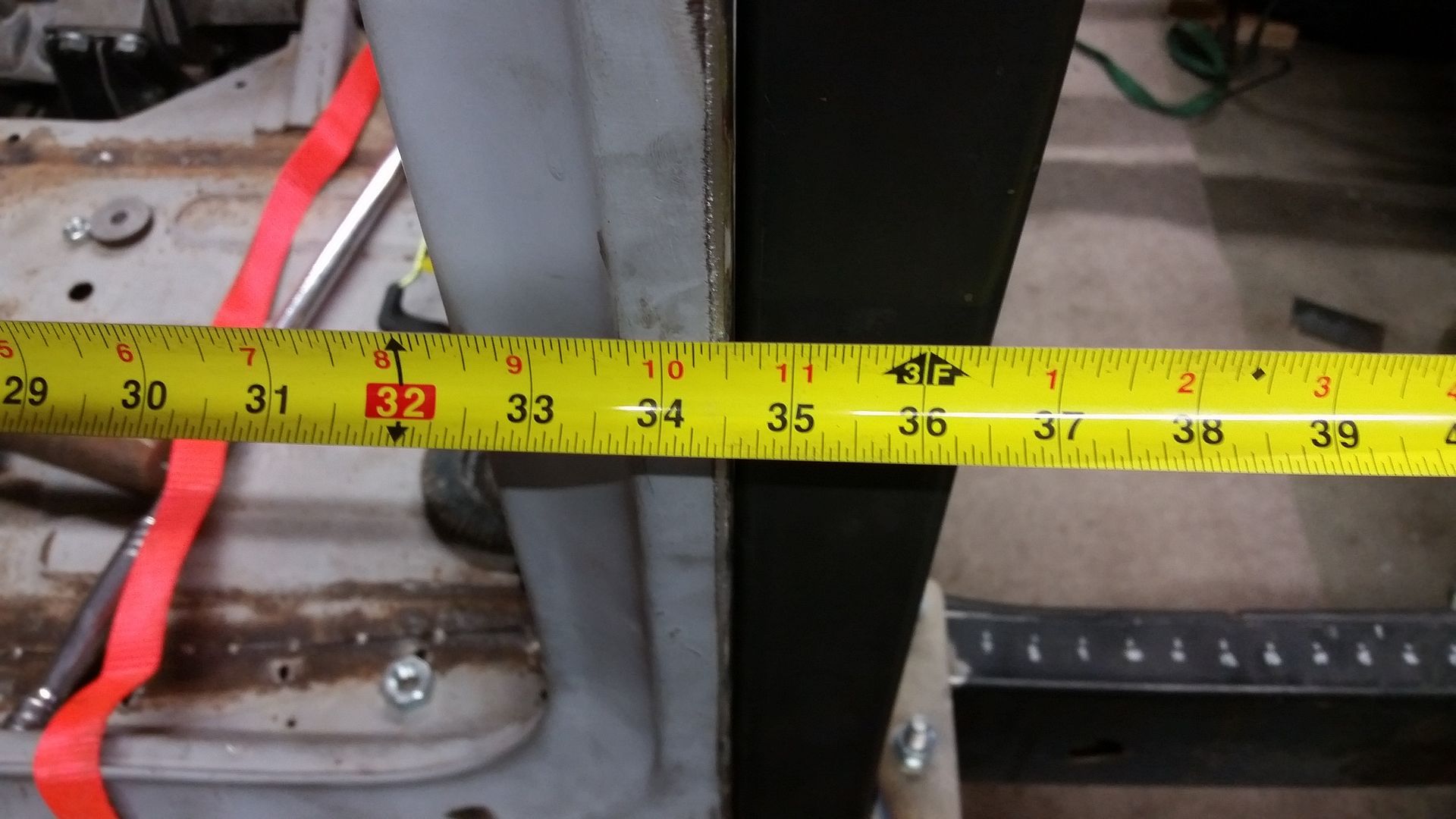
Here are some random detail pictures....


I still have lots more to do with this, but this was the hard part I think!
 

Memento_Vivere

New member
I don't post much, but I read your threads a lot. I read through the do it all dodge, and your jeep build Rango of my memory serves me right. You do amazing work, thank you for all the work you put in to taking pictures, keeping us informed, and the thought behind the process. It helps keep me motivated on my project vehicle, and I really like your building with keeping a low center of gravity. Keep up the amazing work.

Sent from my KYOCERA-C6745 using Tapatalk
 

Metcalf

Expedition Leader
Thanks everyone.

I will be taking a little time to build this next....


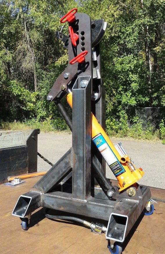
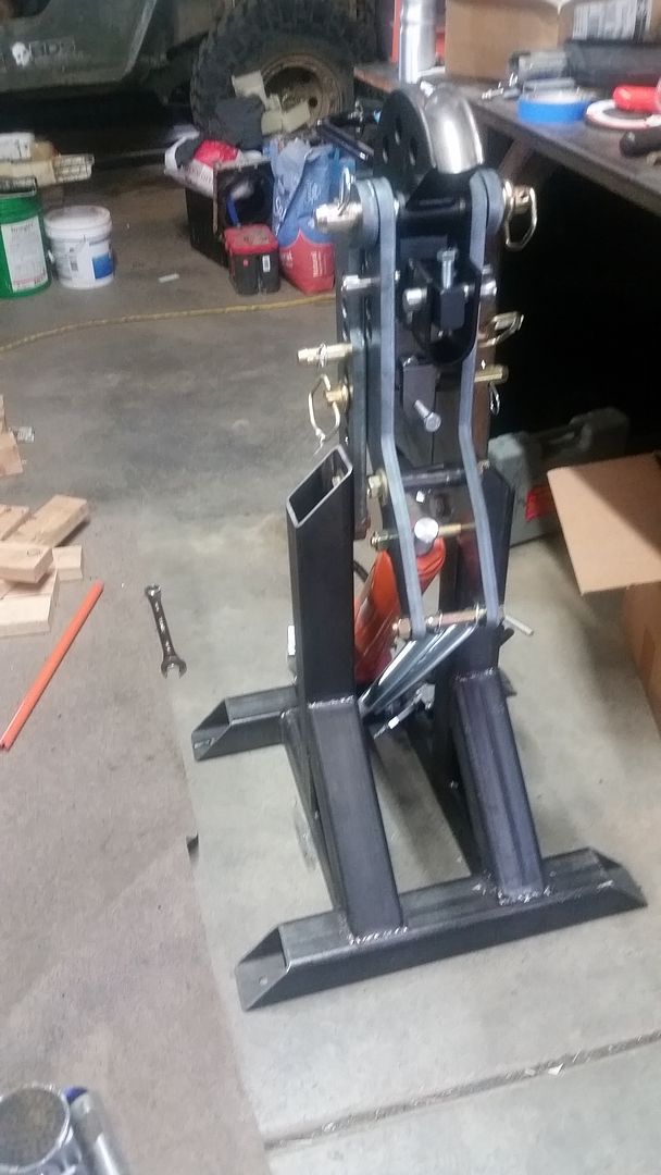
I am finally going to have to break down and build myself a tube bender. I have been putting this off for a few years. I ended up calling in a favor on my flat fender for the 4 bends I needed because of time constraints. I have some half finished arms that I made a few years ago, but decided to start fresh.

A pirate vendor had a great deal going on an arm package, but I think it was discontinued. You can still buy plans however and have them cut locally on a waterjet or laser table.

http://www.pirate4x4.com/forum/tool...lasma-table-vertical-tubing-bender-plans.html

The arms are basically designed to use common Pro-tools 105 dies and is powered by one of the air/hydraulic rams from Harbor Freight.

I picked up the material for the base a few months back. My little HF saw is going to get a workout!

Stay tuned.
 

vwhammer

Adventurer
I am curious what this bender will cost when it is all said and done.
I have been on a budget tool buying binge lately.
Just enough to get me by in my little shop and this would be right up my alley.

Cool build by the way.
 

Metcalf

Expedition Leader
I am curious what this bender will cost when it is all said and done.
I have been on a budget tool buying binge lately.
Just enough to get me by in my little shop and this would be right up my alley.

Cool build by the way.

I don't know if I would call it a 'budget' tool really, you still have the die cost that you will with any bender. The dies are roughly $300 each.

This kit seems to have been about the same cost as a normal 'manual' style bender package from any of the big manufacturers ( $350-400 ) but with the addition of a correctly orientated hydraulic ram. You can retrofit this style ram to a typical horizontal bender, but they are typically cantilevered and don't quite work right. I did get a very good deal on the arm package, and unfortunately the company I purchased from is no longer selling the arms. They are now offering a kit with the cut information for the arms to be done locally. I have a lot of parts cut locally on a waterjet and I know I would have paid more than I did for the old arm package....by a lot.

I have had the hydraulic ram sitting around for a few years, but there may be other options available now. A member on another board came up with a way to power his horizontal bender with a very affordable trailer jack.

Horizontal vs Vertical is probably another discussion. I see ups and downs for either version. I do think that measuring bends in a vertical bender is easier with the digital angle levels and cubes that a lot of people have laying around. With a horizontal bender you pretty much need a degree wheel and pointer. I do like that powered versions don't have to be bolted to the floor or whatever. I will be able to roll this bender around which will be really nice.
 

Metcalf

Expedition Leader
Ok, my tube bender is done, now back to the regularly scheduled programming right after this shop cleaning break....


Metcalf

Expedition Leader
In an effort to show more about how and why I do things.....


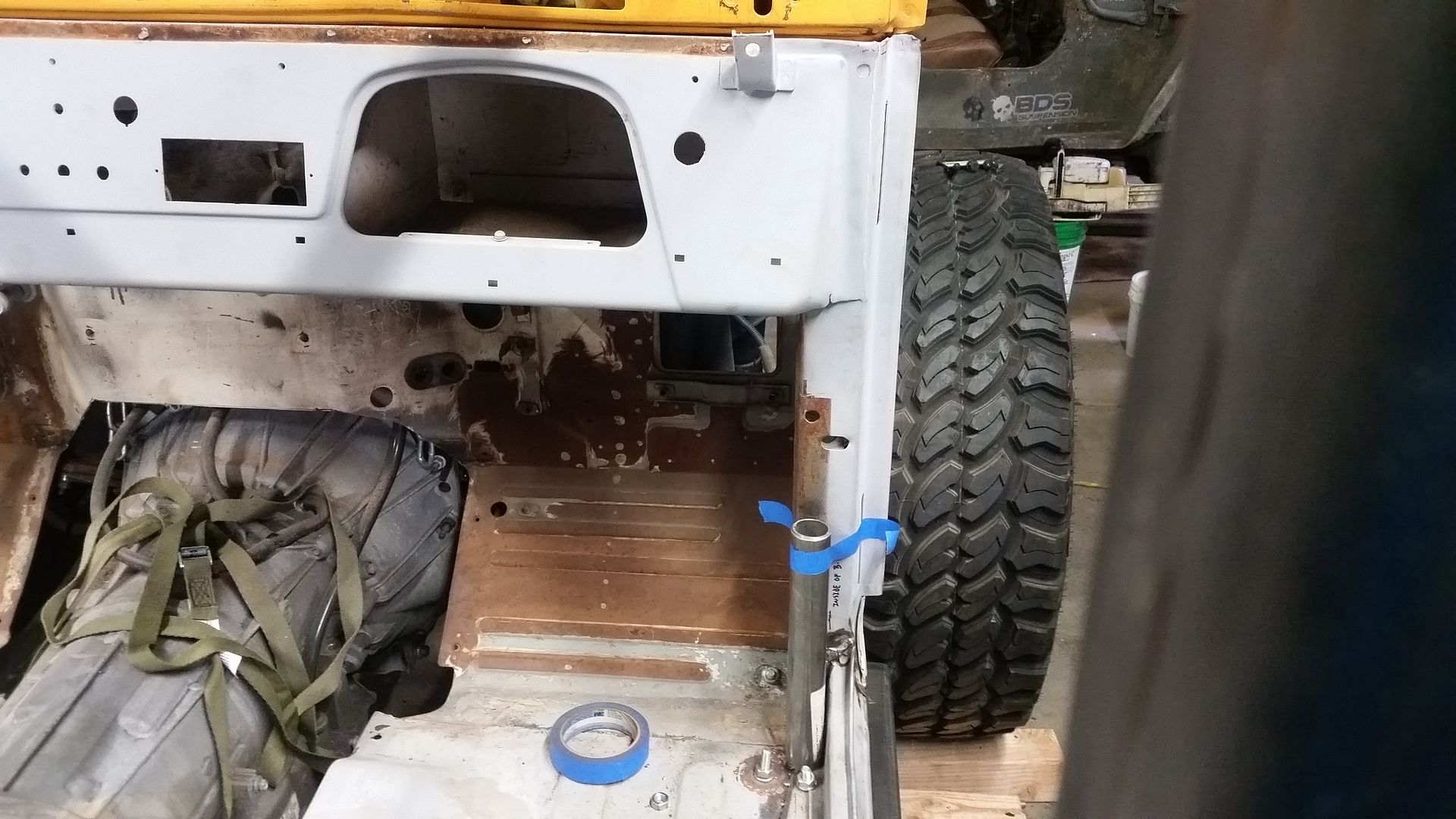
One of the things I wanted to do on this build, and most future builds, was to make the dash removable for easier wiring. Unfortunately, I don't think I can make that happen on this body. After further investigation of the top seam of the dash I noticed that the top seam is much smaller than I had thought, and the top seam is also folded over to make that 3 layers thick. Ugh. I just don't think it is worth trying to completely redo the dash to make it removable.


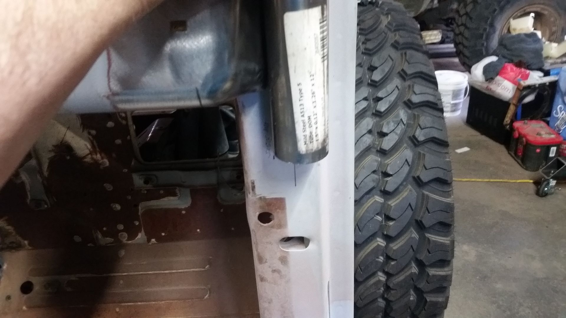
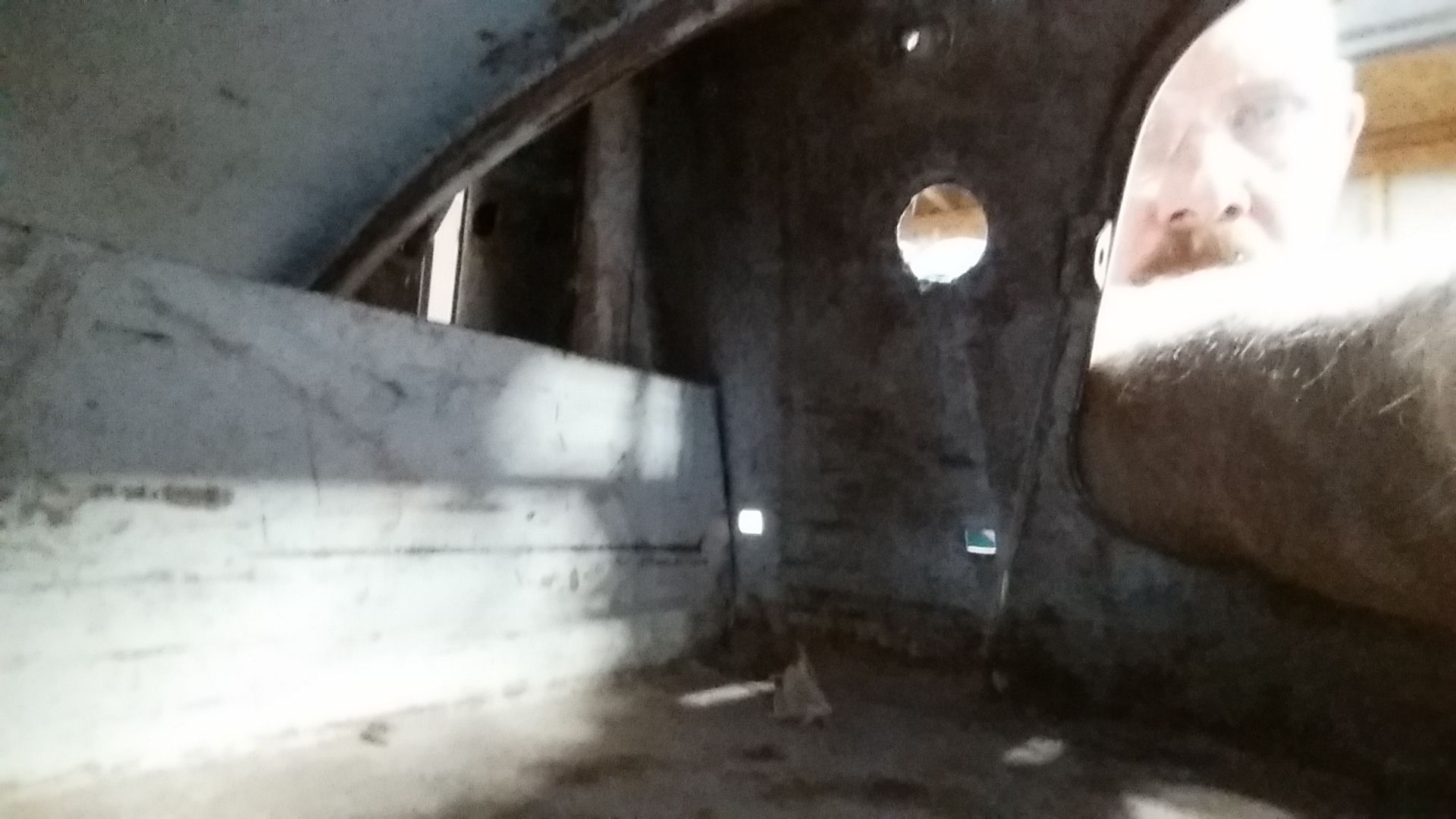
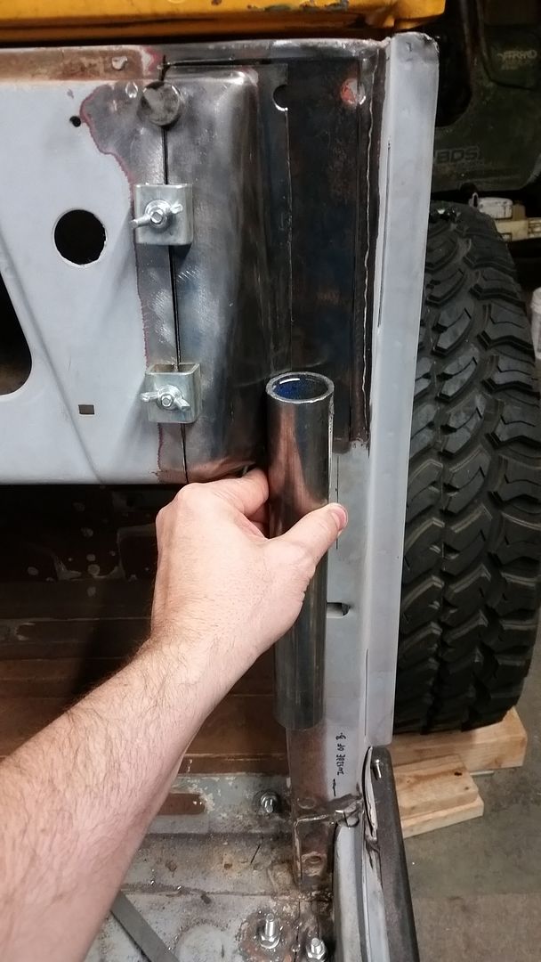
However, this is where I need the A-pillar to be. I want the A-pillar to go completely to the floor ( and then to the frame ) on this car. When I designed the body outriggers and mounts I designed in a little extra space for the tube in this location. Basically it is shoved as far forward and outboard into the corner of the door hinge/cowl support and the inner door opening panel. Don't worry, I will be making a nice 10 gauge cold roll pad/mount for the tube, but this is the 'final' position of the tube. I don't want that tube to be any further inboard because of the already narrow foot area. I want it as far forward so it doesn't get in the way of your feet when getting in and out of the vehicle. If you look above this little short section of tube, you might spot a little problem....dang it...the corner of the dash is in the way.


Well, using that same section of tube, this is how far the tube can be inboard. Darn it. That vertical line below the tube is about where the OUTSIDE of the tube needs to go. I guess it looks like I will have to do some cutting on the dash anyways....

The basic plan is to remove about a 1.25" vertical section of the dash which will allow me to move the 'corner' of the dash inboard enough to clear the A-pillar tube. I will probably also add a dash pad in thicker material that will weld to the dash and cowl panel to provide some intermediate structure for the A-pillar near where the bend will be to match the angle of the windshield.


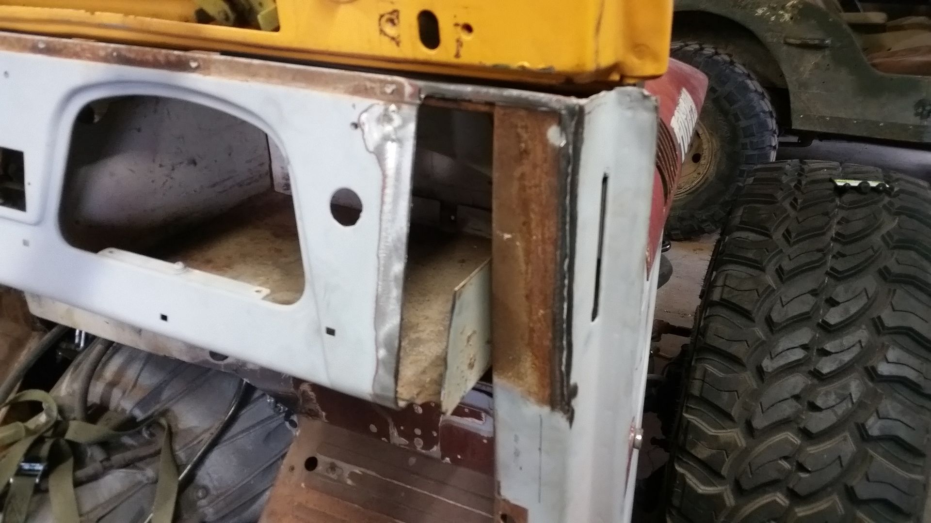
The glove box is sure nice and big! It even has an auto eject feature for small items if they can fit over the wall on the outside! It sure was nice of Toyota to stick a flange and spot weld RIGHT where I need to cut. I need to find a creative and clean way to chop off that flange.....

Stay tuned.
 

Metcalf

Expedition Leader
Ok....let's cut up some stuff!


This is basically where we I left off mentally, but I decided I should probably use some sharpie to illustrate what I needed to do. I basically need to remove a 1.25" section of the 'flat' part of the dash in order to move the 'corner' at the end of the dash inboard to clear the future A-pillar....


Removing the waste section of material was actually pretty easy. I did it all with a careful, read lucky, hand using a 4" angle grinder with one of the very 0.045 thick cut off wheels. I planned the outboard cut to be JUST inboard of the flange for the outer glovebox wall....


Here is the outer wall of the glovebox still attached to the corner. I thought about trying to find those spot welds and cut remove them from the outside, but could not locate them! I ended up removing the waste section to give me access to cut that flange off with the cut-off wheel.


All apart....


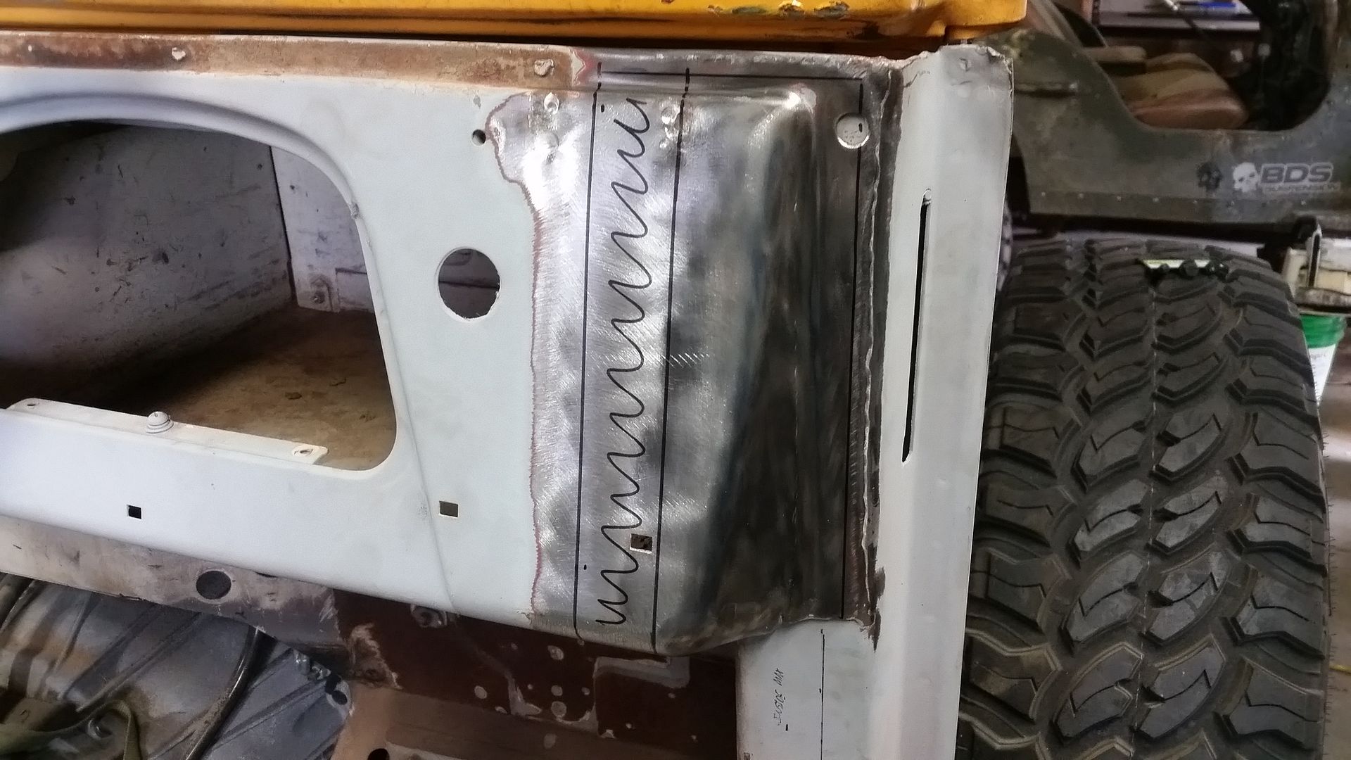
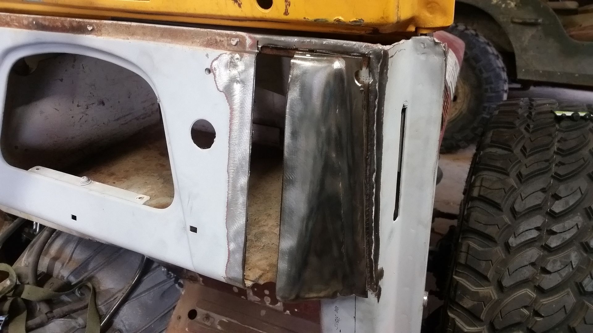
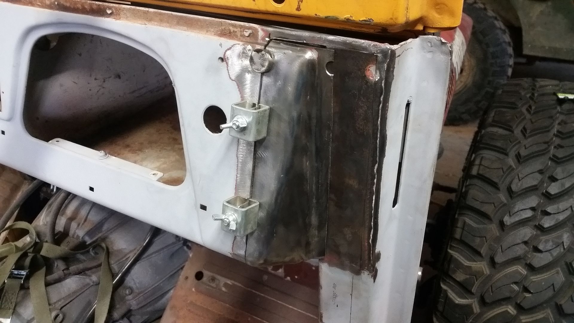
Here is the new position of the corner after everything was all cleaned up. I still have a lot of little things to do. I found a crack in the bottom corner that I need to drill out and weld up. I am planning making a 10 gauge plate that will fit in the new corner which will tie the bend area of A-pillar tube into the cowl structure. Since this cage is basically going to be welded into the body, that panel will be welded to the dash panel. All little details. I need to pick up a spool of .023 wire and a new tip for the sheet-metal work. I don't think I am good enough to TIG all this old metal, maybe some day.


....and that is the reason why. All that to be able to move the A-pillar location over about 1.25"
 

Metcalf

Expedition Leader
Nothing super special last night....just arts and crafts....


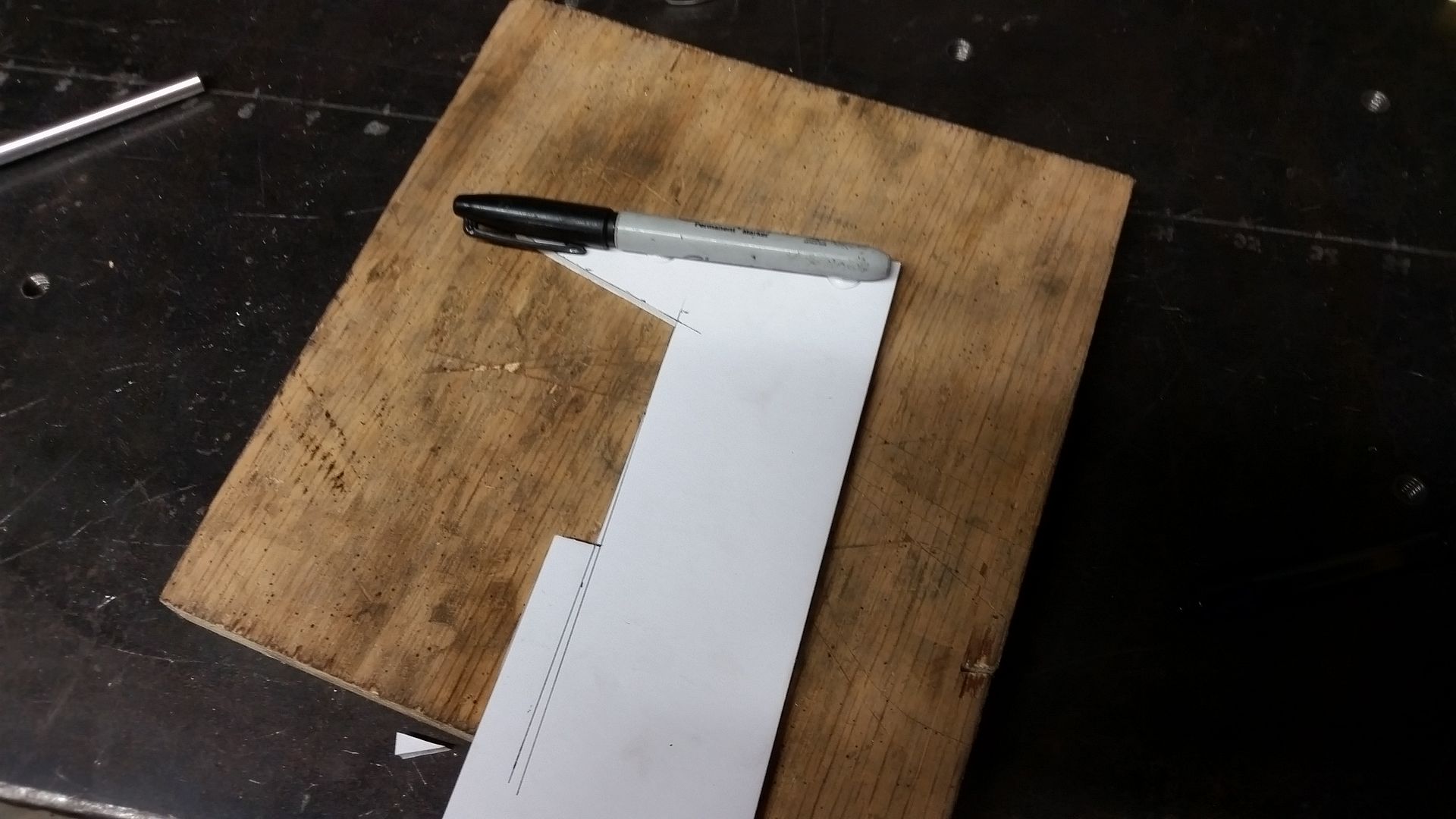
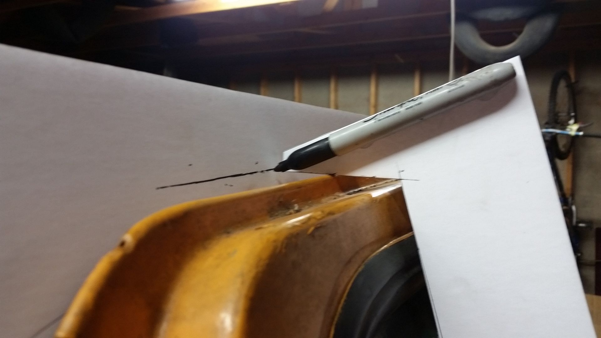
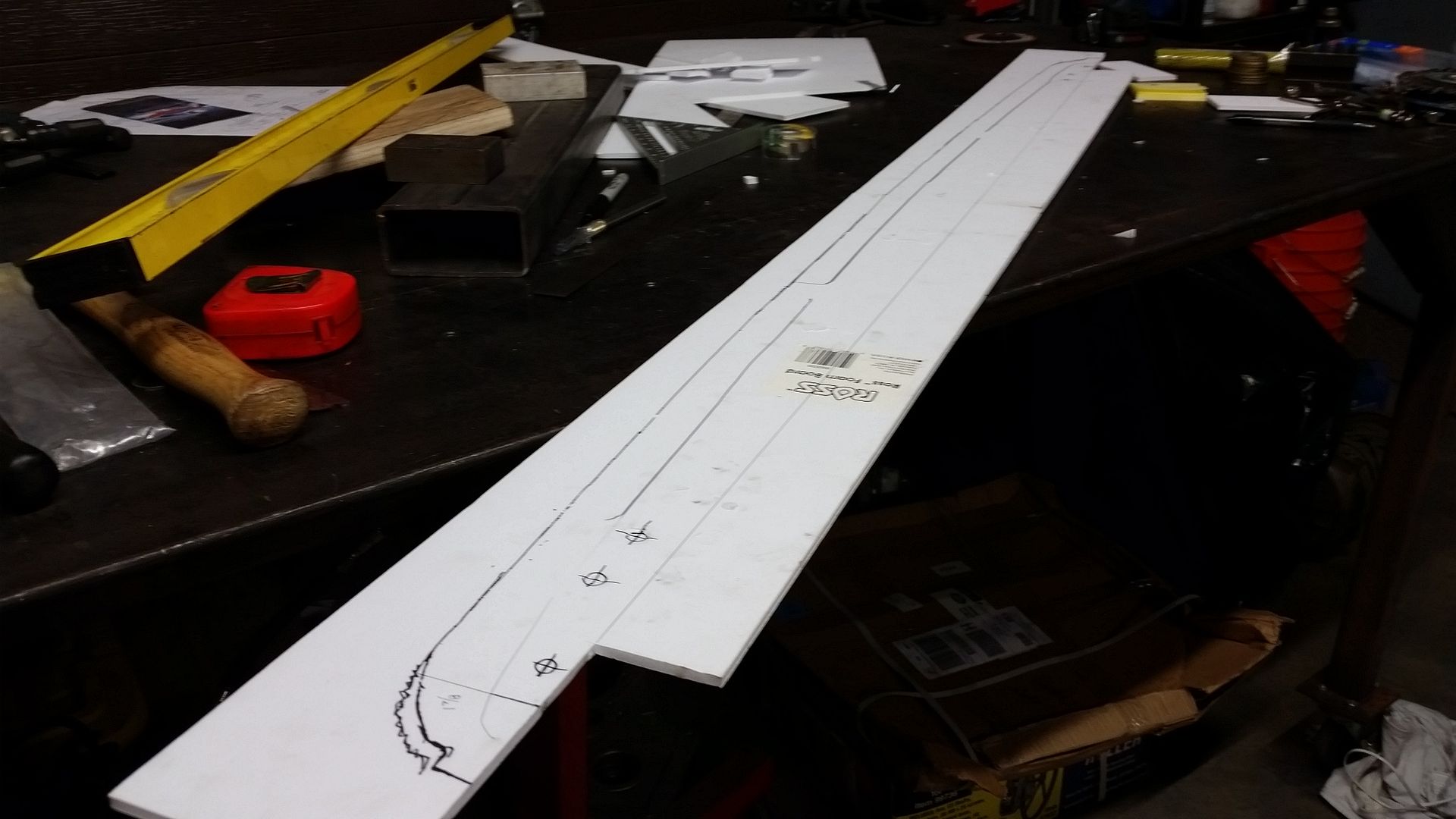
I made this little tool out of some foam board, a sharpie, and some hot glue. It's purpose was to do this....


So I could make this....


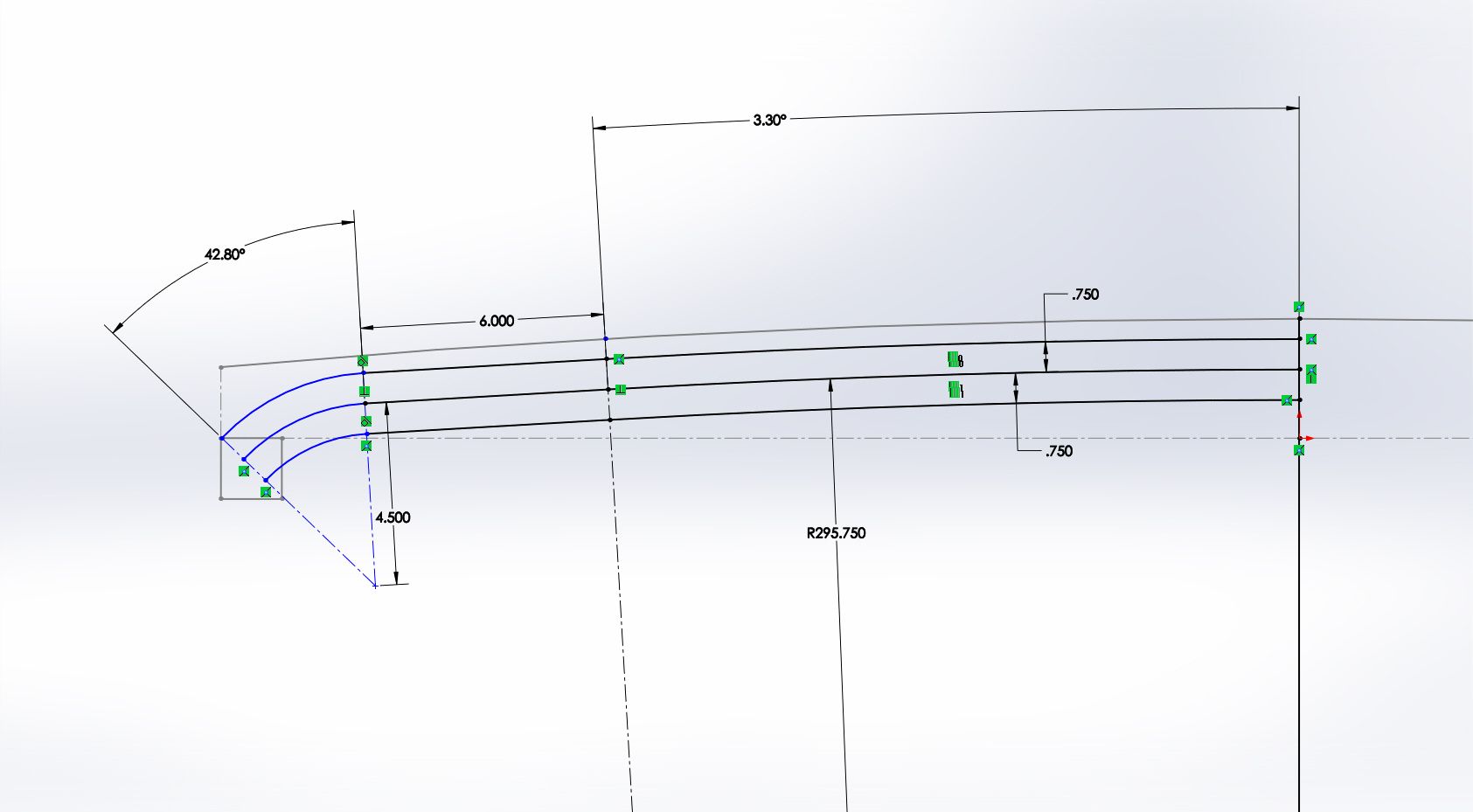
I needed a mostly accurate template of the profile of the windshield frame in relation to the door bars. That will allow me to input that information into the computer which will be handy. I will also be using this template eventually when I have to make some of the tooling for the construction of the top panel in the future....

In the short tern. I converted the data from the template into computer information.


That let me start laying out the A-pillar spreader bar. Unfortunately, that tube is going to have to be much more complex than I would have liked. My initial thought was that I could just roll it. I could I guess, but that will leave a few extra inches between the future top panel ( which will be very close in profile to the windshield frame ) and the tube. After a bit of layout time I think I came up with a way to roll AND bend that tube so that it fits much tighter to the profile of the cage. That should be a decent challenge!
 

Metcalf

Expedition Leader
Just a short evening tonight...


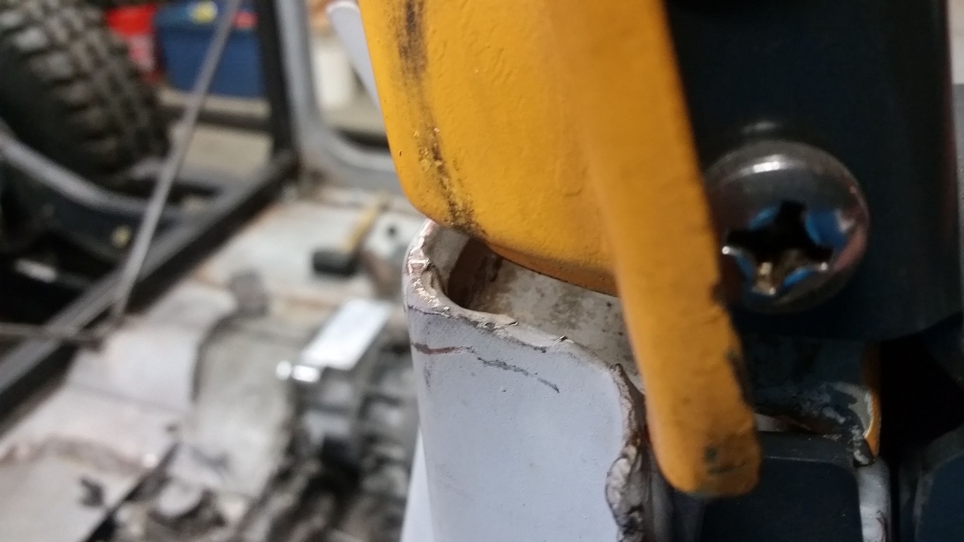
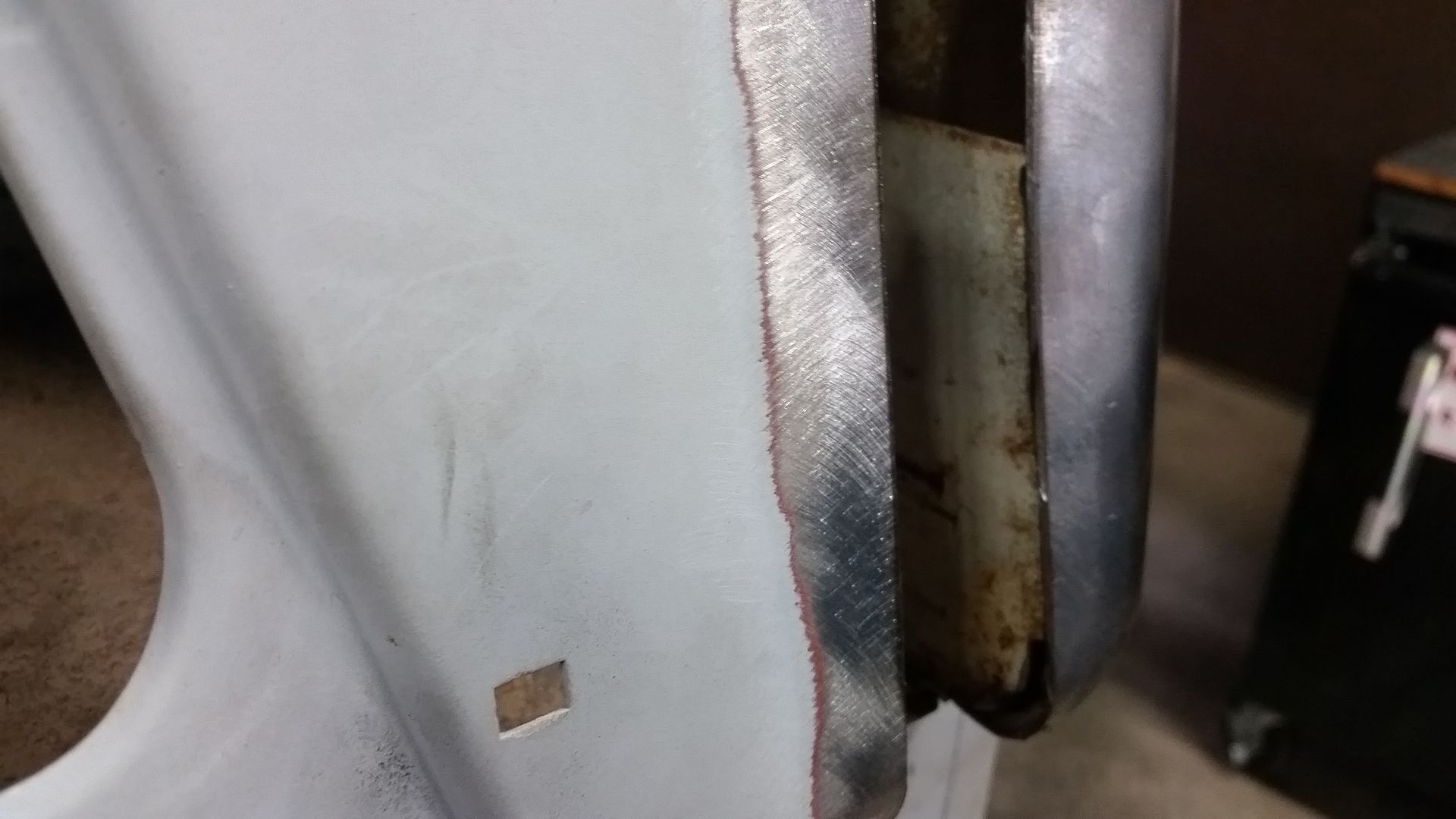
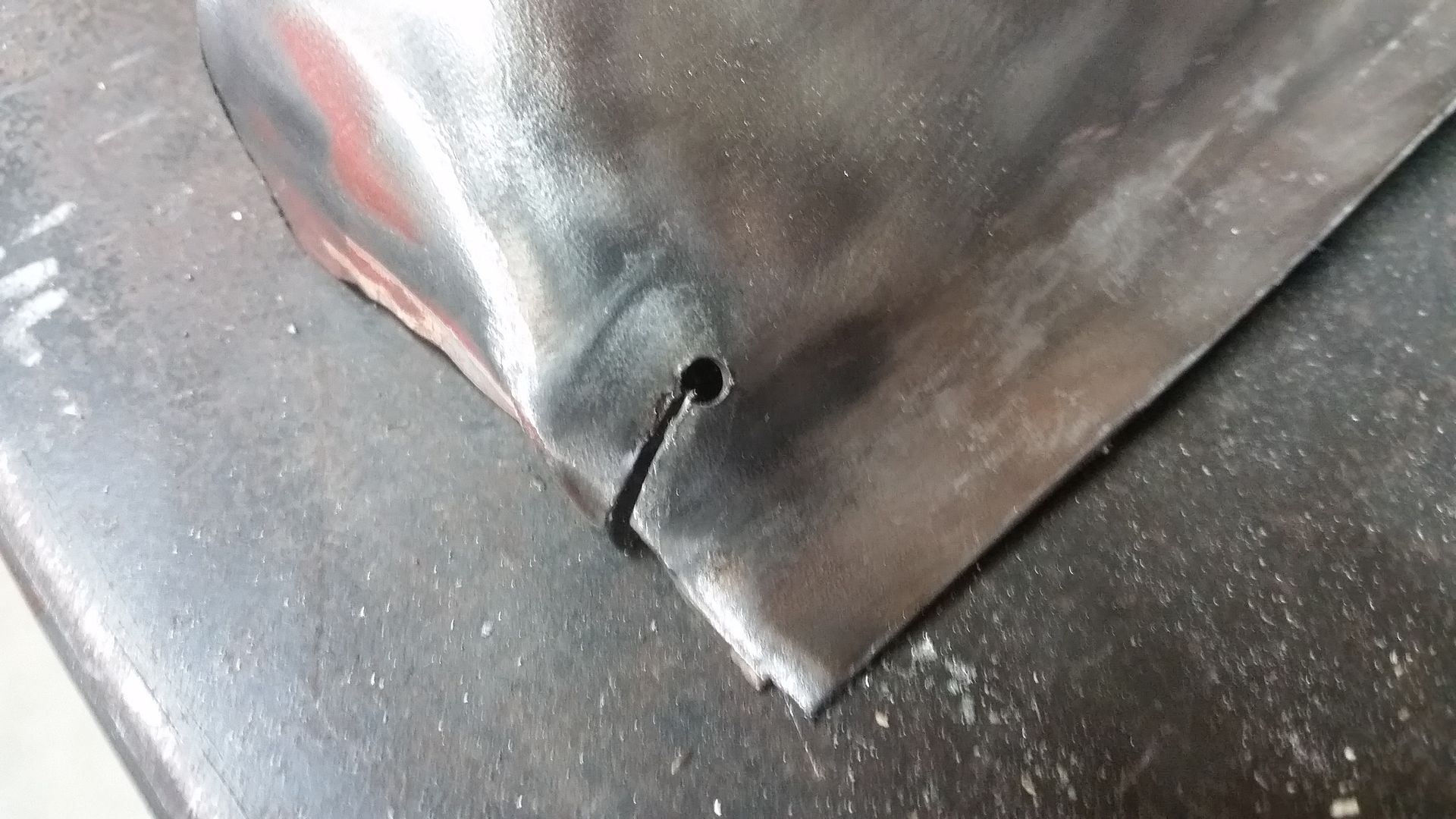
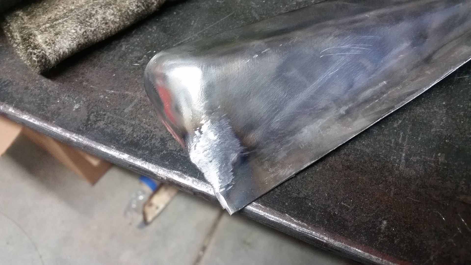
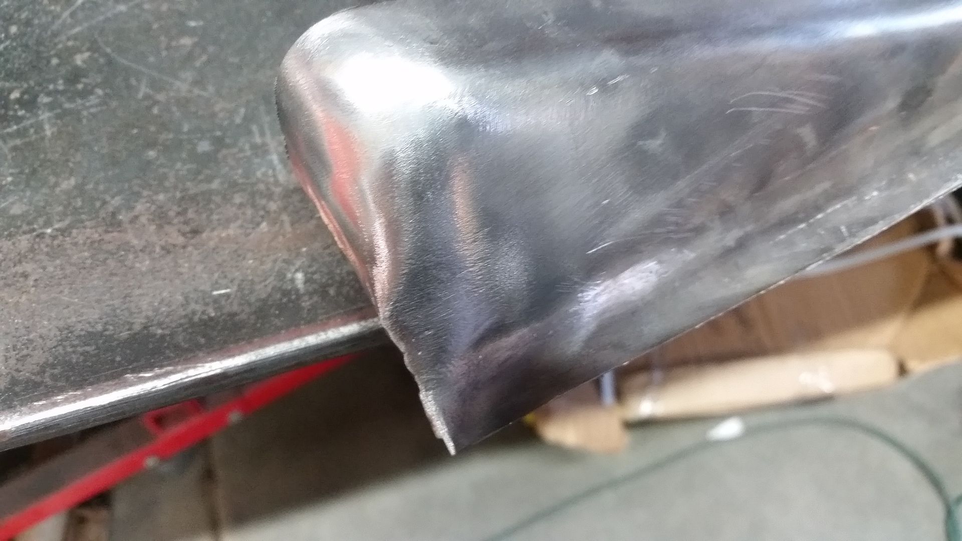
Crack repair in my dash corner. I drill out the root. Grind out the crack a little with a Dremel and small cut off wheel. I try to keep the gap as small as practical. If I can, I weld the back side 1st, then weld the front side....


After a little work with a flap wheel and file it will look like this....


Then I finally hit it with a stiff wire wheel brush to smooth out the finish to match the rest of the panel.


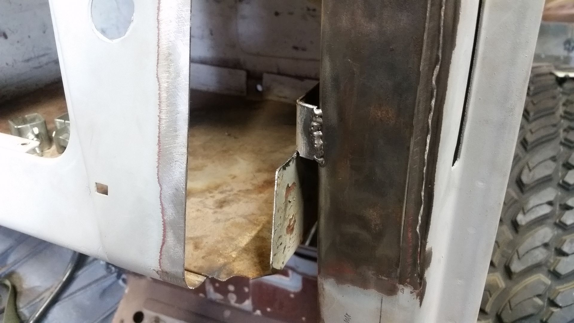
I needed to add a little support back into the outside wall of the glove box. I ended up making a little 1" flap out of the original wall. The root of the flap was drilled so it won't crack out. I bend it over with a little flat nose pliers love followed up with a little hammer and dolly work. Once it was trimmed to fit to the cowl/dash/door support, I welded it into place. This really stiffened up that wall.


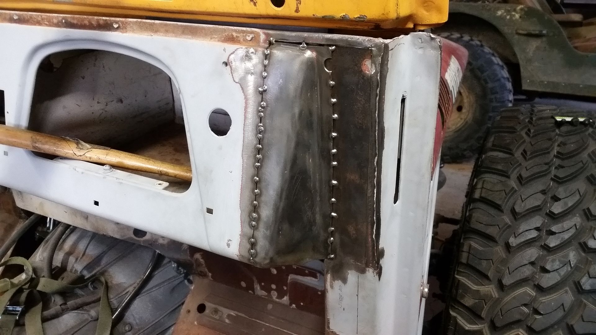
Since all the details where taken care of, it was time to finally fit and weld the corner panel pack in place. This took a little time. I spent a bit trying to keep the inside seam as flat as possible during the weld process. It was nice that I could get to the inside with a hammer or dolly. I typically tack every 2". Hammer and dolly everything flat again. Tack every 1". Follow that with another round of Hammer and dolly to keep it flat. Then split the difference and make a tack weld every 1/2". That is where I am now pretty much. It is good not to rush if possible. If you can't stick your bare hands on the panel your welding too fast. I will continue to split the difference and move around as I completely weld the panel seam.

I will take my time and weld the panel up over the next few evenings to keep the heat input at one time down. It isn't going anywhere now...
 

justcuz

Explorer
Nice work!

I watched an old guy hammer weld a chopped top on a Studebaker Bonneville car, lots of skill and patience required there too.
 

Forum statistics

Threads
185,839
Messages
2,878,740
Members
225,393
Latest member
jgrillz94
Top