Power Observer

Poorboyota26

Adventurer
I have to design and build a project of some sort that will be usefull to me and show what I've learned while at school. A Capstone project.

I've decided to design a power management/observation box for Auxiliary power drains and supplies.

The "box" will consist of the following:

1 12 volt input (I'm thinking 30-40 amp)
1 variable voltage for solar or wind generation
6 12 volt outputs for various needs and in varying amperages
Digital monitoring display

The outputs will increas in importance so that as the input/Battery voltage is discharged the box will shut off outputs from least critical to most critical. Keeping enough charge on the battery for vehicle startup.

The display will have:
Alternator charging amps
batery voltage
solar/wind voltage
solar/wind Amperage
individual draw for each output

when the second to last out put is shut off there will be an alarm and maybe a blinking led to indicate that charging is needed.

I would like from you all:

Input on some of the most comon amperage draws ie, Fridge, Lights that are run while camped for cooking etc, Aux driving lights, Heat blankets, water pumps, Ham/CB radio's.

This system is to help keep batteries from total discharge and avoid dead batteries.

I know there are other systems out there, I haven't gotten that far in my research yet. If any of you would like to post them (links and photos) that would be great!

Thanks for the help!
Kevin
 

Poorboyota26

Adventurer
Oh yeah, the coffee maker!

I've been thinking that 40 amps isn't going to be enough.
Port 1 = 15 amp
Port 2 = 15 amp
Port 3 = 10 amp
Port 4 = 10 amp
Port 5 = 7.5 amp
Port 6 = 7.5 amp

that's 65 amps so I guess a 70 amp input would be sufficiant. That's a lot of draw at once though.

As for myself, I don't use that much when not intransit, 20 amps maybe for an hour tops.
 

chrismc

Adventurer
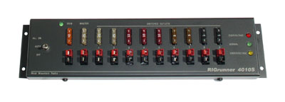
I'd recommend making all the outputs have configurable output amperage controlled by fusing. That would simplify things, as you could just prioritize by "output 1", "output 2", etc... Check out the RigRunner to see how this might look with variable fusing. (http://www.westmountainradio.com/RIGrunner.htm)

4010Sxsm.jpg


Also, as with a house's circuit breaker box, you don't necessarily need the "master" fuse/input to be a sum of the outputs. You only need enough power for the maximum concurrent load. It is highly unlikely that all outputs will be drawing their full amperage at the same time.

Personally, I'd love to see PowerPole connectors on the box. Standardizing on them makes for a much safer and cleaner setup. Basically, I think I'd be looking for a RigRunner with brains. :) BTW, don't overlook the ham radio community as a target audience. Something like this would be an enormous hit at Field Day.
 

keezer36

Adventurer
Personally, I'd be inclined to rely on a good sleeping bag in lieu of a heated blanket. I don't know what their current draw is but anything with a heating element is rarely power supply friendly.

-A fan perhaps.

Is 12v to 120v out of the question? Is there a downside to this or just not part of your thesis statement?

While I'm not knowledgeable enough to draw this out myself at a component level, I would be interested in seeing what you come up with, the arrangement of your voltage limiting, monitoring circuits, etc. if you don't mind.
 

Rando

Explorer
I put together a slightly related system to control the charging/isolation of the dual batteries in my Tacoma. I used an Arduino (Atmel) micro controller to look at the voltage of both batteries, the current to/from the aux and the state of the vehicle (running or not) to decide when to switch the aux battery into or out of the circuit.

You probably already have a plan for how to put this together, and I am assuming you will be using a uController of some sort. My experience was that an Arduino controller worked fine in an automotive environment and it greatly simplifies the coding and hardware. I would also suggest making the hardware as flexible as possible so that you can reconfigure (in firmware) as your needs changed. Maybe just a bus with 8 or so connections, each with a current shunt, voltage monitor and MOSFET as a switch. That way of you decide to change the ratio of inputs/outputs it is just a matter of re flashing your controller. You could also implement other feature in firmware at a later date, such as PWM controlled dimable aux lights. Another thing to consider is that if you have a current monitor on each circuit, and a digital switch, you can implement the 'fuses' for each of the output circuits in software, allowing them to be programmed according to the exact requirements of what ever device is connected. If you sense more than X amps for Y seconds switch off that circuit.


Once you have the hardware built, the software 'features' are almost endless.

I have to design and build a project of some sort that will be usefull to me and show what I've learned while at school. A Capstone project.

I've decided to design a power management/observation box for Auxiliary power drains and supplies.

The "box" will consist of the following:

1 12 volt input (I'm thinking 30-40 amp)
1 variable voltage for solar or wind generation
6 12 volt outputs for various needs and in varying amperages
Digital monitoring display

The outputs will increas in importance so that as the input/Battery voltage is discharged the box will shut off outputs from least critical to most critical. Keeping enough charge on the battery for vehicle startup.

The display will have:
Alternator charging amps
batery voltage
solar/wind voltage
solar/wind Amperage
individual draw for each output

when the second to last out put is shut off there will be an alarm and maybe a blinking led to indicate that charging is needed.

I would like from you all:

Input on some of the most comon amperage draws ie, Fridge, Lights that are run while camped for cooking etc, Aux driving lights, Heat blankets, water pumps, Ham/CB radio's.

This system is to help keep batteries from total discharge and avoid dead batteries.

I know there are other systems out there, I haven't gotten that far in my research yet. If any of you would like to post them (links and photos) that would be great!

Thanks for the help!
Kevin
 

Poorboyota26

Adventurer
MAN, Rando, You and I need to get together over a beer!!! sounds like you and I have the same Idear! I do want to keep it as simple as possible though. I like the idea of programmable and flexible but I don't want to overwhelm myself for a school project. If I were going to produce these I would make it uber flexible for as build orders. I think I might build a couple and sell the spares to make up for the cost of the project one though.

Seriously though, if you are in or around the Denver/Ft.Collins area I'd love to pick your brain for ideas and problems you have had. Send me a PM if you want.
 

Poorboyota26

Adventurer
How many people would be interested? A couple of my professors want one for RV purposes and were wondering what they would cost, and if I'd thought about marketing them. I guess it should cost somewhere in the $100-200 range. I have about $40 in parts assembled and am only 40% through the process. I still have to order the IC chip and figure out a way to talk to the chip using a laptop or desk top. I would like to set it up for USB 2.0 but we will see how much work that takes, and if the chip that I get for it can talk via USB. It's also been mentioned to me to use a full on microprocessor. This would be way overkill but extremely "tunable" for those people that want to play with it.
 

wrcsixeight

Adventurer
I realize you are looking to build you own, but similar devices already exist for about 180$ to 300$

Like the trimetric link 10 or link 20.

I have a MPPT charge controller (Blue Sky SB2512i) for my solar system and it's battery monitor(Blue Sky IPN pro remote) which does most of the things you list.

It will not tell the load of an individual device unless that is the only device being powered. If the sun is out and you are using some electricity, you must do some math to figure out how much that device is drawing. If the engine is running and the sun it out, and you've got some loads happening, I must subtract the solar amperage from the overall net into the battery amperage, but it is still guesswork as to how much amperage the alternator is actually making.
It also only goes to a tenth of an amp or volt.
It records the highest battery voltage and the lowest.
It records the Solar amps produced, and total amps used.
It does count the amp hours in and out of the battery and give a percentage. Mine also adjusts the acceptance duration, and voltages as well as float voltage and amperage of the charge controller.

So it would be neat to see a readout of exactly what each circuit was drawing/producing as your idea does.

Here are most of my electrical loads at 12.8 volts, engine off.

Fridge ----------------------------2.4/ 2.5 amps and a ~30% duty cycle.
Fridge fans ------------------------0.1. to 0.2 amps.
Mv 50 air compressor---------------18 amps no load 22 amps at 100psi
LED lights ------------------------- less than 0.1 amps each.
Incandescent light-------------------0.8 amps
7" flat panel LCD TV------------------ 0.7 to 0.8 amps depending on screen brightness
Laptop(DC to DC converter)--------- 2.3 to 7.4 amps depending on task
Muffin fans----------------- -------0.1 to 0.7 amps depending on fan/ fan speed
water pump ----------------2.3 amps
Stereo---------------------0.8 amps to 4.9 depending on volume/bass
Cell phone charger----------less than 0.2 amps.
800 watt msw inverter
no load---------------------0.8 amps
Inverter powering 6 amp belt sander--------66 amps under load.
Inverter powering laptop -----3.6 to 8.9 amps depending on task


Ignition on, engine not running.
Ready to start.--------------3.5 amps
Blower motor on high--------17.5 amps
In tank Fuel pump---------- 4.3 amps
Blower motor on high--------18 amps
low beams ------------------15 amps
high beams -----------------22 amps
Fog lamps-------------------12 amps

I have a rebuilt Autolite "130" amp alternator.
The most amperage I have ever seen is 64 amps, right after starting with batteries below 80%SOC.

I have seen the starter motor take 124 amps, but there is a delay in the reading, and my engine starts very quickly, so I imagine it can pull well more than that.
 

Forum statistics

Threads
185,783
Messages
2,878,185
Members
225,329
Latest member
FranklinDufresne
Top