VanIsle_Greg
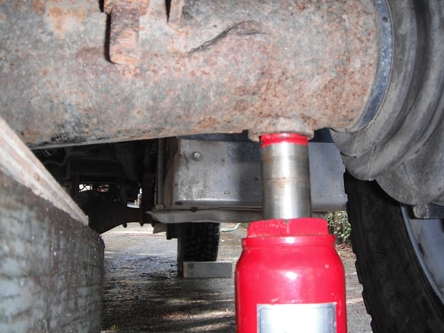
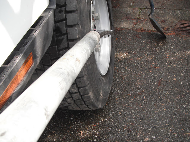
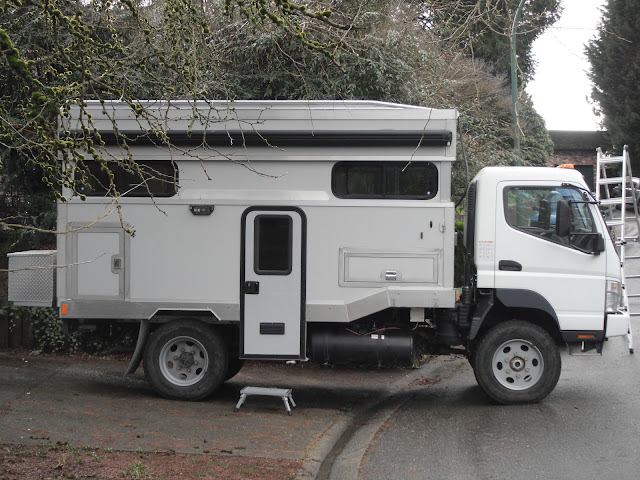
I think I need a bigger truck!
Looking excellent.
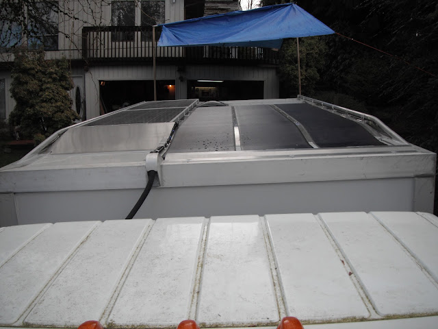
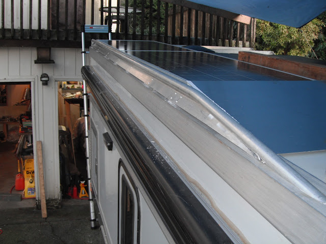
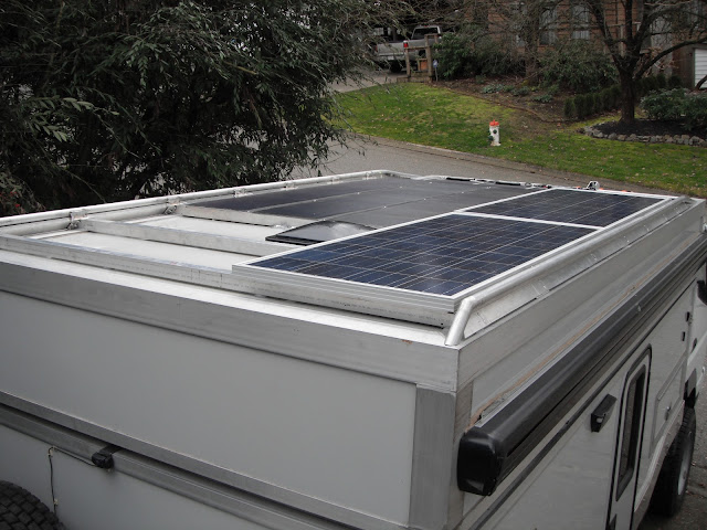
For the interior delamination/sag have you also considered drilling some holes and injecting thickened epoxy up between the core and skin and prop it back in place with it cures? In concert with the cool rack on top your roof would be back in tip to shape.
As far as pumping the epoxy it's pretty straight forward - Just drill a hole and syringe the epoxy in. The diameter of the holes should stop the syringe (which has a tapered nozzle) such that there is a tight jam fit. The pressure comes from your thumb on the syringe - which is considerable (& I think could be calculated using the known diameters of the tube & nozzle hole plus your thumb power..) I usually cut the nozzle back for a bigger hole when using the typical small syringes from epoxy suppliers. I think they would be big enough for what you are doing - they refill quick....This system will pump the epoxy fine...USE A SLOWER SET EPOXY AS THE PRESSURE IN THE SYRINGE GENERATES HEAT...(or just have a bunch of syringes on hand...) - now it gets more complicated.
If the delamination were between solid layers you'd just pump the epoxy into the void while the piece sags then jack it into place & catch the excess epoxy as it comes out. It this case I think the epoxy should be thickened just enough to keep it from flowing from the holes after you've jacked it into place. One approach would be to drill a number of holes maybe 1" -25mm apart over the entire area of the delamination. The spacing is a variable dependent on how well the epoxy spreads within the laminate - which in turn is dependent on the thickness of the epoxy - (if you've thickened it with silca of whatever) AND the nature of the void you're pumping the epoxy into...
If the core material is compromised, meaning the failure is within the core with the exterior skins still well bonded you have to "rebuild the core" by pumping thickened epoxy into the core - so your hole depth and epoxy mix is critical.
If the top laminate and/or the bottom laminate has separated - and it's often difficult to tell which - the job is to get your epoxy to rebond to the core. Generally a shallow hole works for this if your core is OK and of the closed cell type - if it's a honey comb type...your a bit hosed because the voids are big...
One sure solution if you can't really tell what failed - the core or the skin bonds - is to drill a series of holes maybe 1/2 in dia - 13mm from one skin to the other and fill them with a structural epoxy mix. These tubes (called an annulus) structurally replace the core by bonding the skins together. You can just drill a small hole then use an allen wrench in a drill to make the hole in the core - saves time refinishing the surface...
The sizing of the annulus's is seat of the pants...more smaller holes or fewer bigger holes. With a honey comb type core you might be able to use the honey comb cells as the epoxy filled annulus.
In practice I usually use a combination of all these when repairing cores (short of the horror of removing one skin, replacing the core & re-laminating). It will end up heavier & wouldn't be a great idea in a airplane wing...but it's a good if gooey fix. Moe

I think thickened or lightly thickened epoxy would flow through a small tube just fine. The nozzle on my dispensing pumps only has a 1/8" hole or so.
I agree. If somebody's hot to calculate something I wonder what the PSI of a 1/2" dia syringe with a 1/8" outlet and 10 lbs of pressure on the plunger would be? I dimly remember pumping 5 or so ounces into a laminate void with a small syringe...you'd be surprised how much material you can pump with a small syringe...I think thickened or lightly thickened epoxy would flow through a small tube just fine. The nozzle on my dispensing pumps only has a 1/8" hole or so.
I agree. If somebody's hot to calculate something I wonder what the PSI of a 1/2" dia syringe with a 1/8" outlet and 10 lbs of pressure on the plunger would be?
I agree. If somebody's hot to calculate something I wonder what the PSI of a 1/2" dia syringe with a 1/8" outlet and 10 lbs of pressure on the plunger would be? I dimly remember pumping 5 or so ounces into a laminate void with a small syringe...you'd be surprised how much material you can pump with a small syringe...
One idea is to drill two holes at opposite ends of the delamination - pump until epoxy comes out the other hole - if the delamination is not long & narrow you can do this and just plug the hole (toothpick?) when the epoxy comes out then drill another small hole around the "circle" of the delamination and repeat till you are confident epoxy has filled in the voids. It works...
Looking at your core I'd say you can just rebond with liquid epoxy pumped into the space between the foam filled core & the skin. You would have to do both top & bottom though...wouldn't you? I'm assuming the core is sound, so you have to rebond the skins top & bottom. Light tapping on the skin can give you a good idea if the skin has lost its bond so maybe there's just one skin to rebond? Depends on the sag...
A major question is do you pump the epoxy in with the panel jacked into the desired shape...or pump it in then jack it up. My inclination is to make sure there's space for the epoxy to flow into THEN jack it up & let the excess flow out. It's a good question...
Best thing is to use a vacuum pump - jack it up, drill two holes and suck epoxy from one to another - I've seen entire boat hulls re bonded this way by repeating the process several square feet at a time. Moe

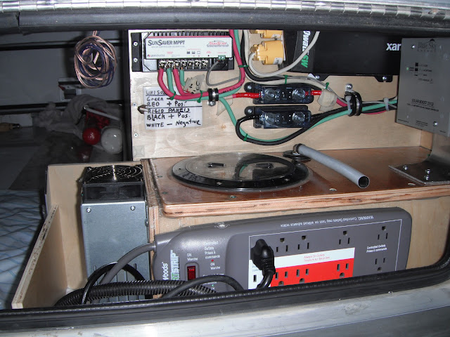
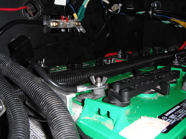
 ) Installed the shunt for the battery monitor which is now useable after being mounted in the fridge cabinet for one year. I had also been just using one starter battery for a while but it did not turn the engine over well in the winter so I squeezed in the other battery. Now there are six batteries in that one little aluminum box?? They just fit in there and hardly any room to move about but I did fill the gaps to tighten it all up.