Rango.....1942 Willys MB

Metcalf

Expedition Leader
And now I need to clean stuff.....


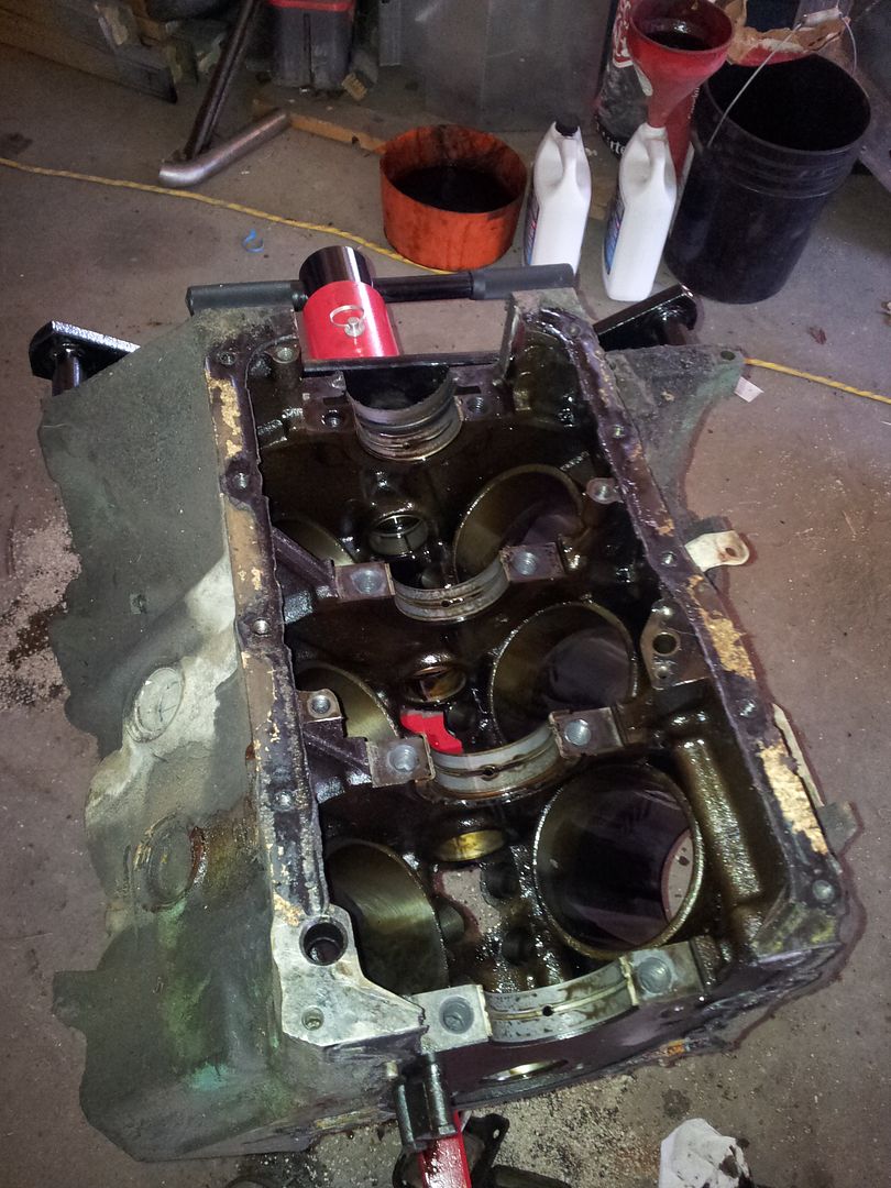
Everything in the bottom end looked really good. I will be reassembling the shortblock with new seals, bearings, and rings. Everything is standard as far as I can tell. I will probably ball/flex-hone it and clean it really well.

I plastigaged some of the mains and rods. Everything was about .001-.0015

Nothing looked out of place or different between any of the bearings. The crank measured standard/standard

Anyone use one of these style ring compressors?

http://www.summitracing.com/parts/sme-90a3700/overview/
 

Metcalf

Expedition Leader


All cleaned up and ready for assembly. This was 1 dose of oven cleaner, 2 doses of engine cleaner, 4 cans of brake cleaner, and a lot of elbow grease. I ran a ball-hone/flex-hone on the cylinders to hopefully get a quick ring seal. The cylinders are still measuring standard bore. This was just 10 seconds each direction on a 240 grit hone. Then lots more cleaning, air drying, and oiling. Its all safe back in the shop with a fresh bag over it.

I need to get a ring and bearing kit coming so I can assemble the short block next weekend....
 

Metcalf

Expedition Leader
Yarg.....what an afternoon....


The crank is back in the block along with a new rear main seal and bearings.

Who ever invented the new rubber rear main side seals should have one shoved up there nose! Those things are a total pain in the rear. I like the new modern sealing technology but holy cow I was frustrated.

They say in the instructions to just slide the new side seals in with the rear main bearing cap. Yeah right. It took a miracle of holding 3 things while tapping with a nylon hammer to get everything together all while hoping the upper half of the rear main bearing didn't fall out of the cap. On about the 10th try I got it. Good thing I happen to have a spare pair because I cut one on during the first 5 tires.

Everything went together well. The thrust was on the big end of the tollerance but maybe my technique was off. The mains spec'd out well unless I was reading the plastigage wrong. I have to keep reminding myself that wider means less gap. I have found that using tweezers ( don't tell the misses ) works the best for setting in the little piece of plastigage material. I'll put them back, swear!

Anyways. I didn't take many pictures....

I am still cleaning pistons, 3 are clean enough to go back in, 3 to go.....

The carbon buildup on the piston tops is a total pain in the rear to get off. I usually call it good after they soak for 48 hours in Chem-Dip and get a nylon brushing every 8 hours along with a water rinse.

I should be ready to install the pistons in a few more days.
 

Metcalf

Expedition Leader
Finally a little progress!


This thing works GREAT. You basically set it for a slip fit on the piston and forget it. I didn't have to adjust it once after setting it.

Do this six times and you end up with.....


Everything seemed to go according to plan. Everything was within spec. The ring gaps where on the top end of the tolerance but the block a worn stock bore that was ball-honed. I expected it to be a touch loose.

Vacuum caps make great protectors for the connecting rod bolts when you are inserting pistons. My best tip, don't stick the vacuum caps all the way on the bolt because they are a pain in the rear to get off! They only need to be over 2-3 threads.

Use lots of lube :)

My cam kit showed up! I need to separate out some parts for the head builder. The heads get sent off next week.

I need to go find/make a handle for installing the cam. I also didn't see any of the Comp Cams special lube in the box? I need to look again.

Cam and timing chain is next......
 

Metcalf

Expedition Leader
Some interesting parts are showing up.....


Griffin 24x16 radiator, 1.25" dual core! Dual pass!

Take that cooling problems!

Overall I am pretty happy with the quality. There where some small little issues but nothing deal breaking. I think the biggest odd issue for me is that the top of the radiator had a flange that is pointed towards the radiator ( read no flanges to attach anything to ). The flange on the bottom is pointed down and goes give you something to attach things to....like a shroud. I do have some ideas, but it will be a little more different than I was thinking on going.

The drain port is located lower than I thought. There was a small weld divot in the drain fitting that will need a little file cleanup.

If I had to be picky the edges of the inlet/outlet are pretty rough. I will have to touch those up.

I have a new fan in the mail that should be here soon. The fan relay pack is here. Hopefully my cylinder heads show up early next week so I can finish assembling the wheels. Tomorrow I think I will build a brake for my press....

A few misc pics....


Metcalf

Expedition Leader
Just a bit more this weekend...I'm holding out on tearing the old engine out until I have the new heads in hand.

I did start cleaning some more engine parts...mainly the timing chain cover, oil pump, water pump stuff.


Well there's your problem! I think having one side of the engine completely blocked off for coolant could cause a few issues. This was on my spare engine. I wonder what caused it. The water pump looked ok, this major passage was just completely plugged....


There little flat head screws that hold the oil pump cover where also a pain in the rear. I need to get something different for the reassembly.

I also pulled the old style rope front seal housing out of the timing cover in anticipation of installing an updated version.

The intake manifold, oil pan, and a few other misc parts also got a good bath. They still need some wire wheel love but they are getting close.

Hopefully my rebuild cylinder heads will be in my hands this week!
 

Metcalf

Expedition Leader
Some more misc stuff....


I had one water pump bolt break off. That sucked. I tried to not let it bother me until I looked at the price for a nice cover. Since the cover was aluminum and the bolt was steel I was able to weld a nut to it, it was broke off flush of course!

My tip for that is to weld up a good ball of solid metal on the broken bolt BEFORE you try and weld on a nut. Then find a nut that is slightly larger than the weld ball and weld the new weld ball to the nut. Don't try and do it all at once. I think the heat from the weld also helps break things free. MUCH easier than trying to drill it and using a small ez-out. It was a 1/4-20 bolt and I ended up using a 3/8" nut and that worked out just perfect.

PHEWWWWW...and a bit forehead wipe on that one. A new front cover isn't cheap, and isn't correct for the 225 timing pointer from what I have read.

Back to cleaning and prep. My heads where suppose to be done late today. We will see.

Here is a picture of my existing radiator/fan/water pump clearance for reference....


It is about 9-9.5" from the back of the grill to the water pump snout. My existing 3-core brass radiator is about 2.5" back from the grill. The dual electric fan motors actually pass the water pump.

I need to fit my new 3" thick radiator and Volvo electric fan in the same space. I think this is going to be fun......

Anyone have any rough guidelines on how far back the radiator should be from the grill slats to allow air to flow into the entire core of the radiator. I can see if the radiator was basically touching the back of the grill the slats could be blocking a decent amount of the area of the core?

The other question is how far to space the fan off the radiator? Basically how deep the fan shroud should be?
 

Metcalf

Expedition Leader
My new electric fan showed up yesterday.....


Some rough measurements of the fan ( and radiator ).

-Radiator bottom flange height, 3/8"
-Core width, 19" ( both inlet and outlet welds get into that aea )
-Core height, with bottom flange, 15.188"

Fan-

-Overall mounting flange diameter, 17.75"
-Blade diamter, 15.25-15.5"
-hole needed in shroud for fan, 15.75"
-Fan depth into shroud from mounting surface, 1"
-Fan height out of shroud from mounting surface, 3.25" ( to the rear tip of the motor housing )
-Rough motor shape, 3.25" diameter, 1" tall
 

Metcalf

Expedition Leader


All the cool kids are going it, so I figured I would jump on the bus for my upcoming radiator mount project.

I spun up the lathe and turned a 1" dimple die. I gave it a test on some 14 gauge scrap I had laying around. I think it turned out ok?

While I was playing on the lathe I started cutting up some scrap for a press brake idea I have bouncing around in my head. I want to be able to do some opposing flanges and that complicates things a little bit.

More soon...
 

Metcalf

Expedition Leader
I got my press brake idea all tacked together.


I built it a little bit the same and a little bit different than what you see. It is all made from scrap material I got at bin at work.

The bottom plate is 6" wide, 1/2" thick material. There are some 1x1, 1/4" angle reinforcements on the bottom that lock into the HF20 press bottom frame. On top of that is a 2x4", 1/4" thick box tubing. The actual female die is made from two pieces of .625" square stock.

The top die is a piece of 1" x 1.5" bar stock with a 22" long piece of 1x1, 1/4" angle that forms the 90 degree male die. There is a small piece of 2", 1/4" wall, square tubing with a set screw to hold the top die to the round press shaft.


Here was the 1st bend on some 14 guage material. The entire assembly was only tack welded.

So why the bottom offset you say?


Basically one of the major limitations I see with the normal units you see is that you can't do any opposing bends. With the bottom die raised up off the base you can do jog type bends within reason. The way I set it up the flange can be 4.625" long and the next bend can be 1" away. It lets you do things like this....


Overall I am pretty happy with the bend quality. The radius is pretty tight and crisp. If you lightly bottom the die out you get pretty dang close to a perfect 90 bend. There is a little spring back, but on thin material you can adjust to that perfect 90 with your hands or a dead blow pretty easy.

With the way the upper die is designed you can do U-bends also on each side as long as you have an opposing piece of scrap material to equalize the bend force.

Its not done yet. I still need to add some guides to keep the upper die inline with where it needs to go. I also need to add some set screws to the press frame to help keep it square to everything else.
 

Metcalf

Expedition Leader
Nothing that interesting.....other than I have a complete engine now!


And in primer....


Now I feel pretty good about pulling the old engine! A few coats of paint and it should be ready to go in. Then the accessories and cooling system.
 

Metcalf

Expedition Leader
It was a kinda interesting weekend.....


I did this.....


This was all ready to go into its new home....


Then this happened!

When I was installing the engine I think the input shaft didn't go into the clutch disc splines correctly. In the process of lifting, shifting, and shaking it around somehow I shattered the back side of the clutch disc. Crapola...

I came in that evening, Saturday, and ordered up another clutch disc. It should be here Wednesday I think.

That was kinda demoralizing, it totally ruined the plan I had going for the order of things. All I could do was get back out in the shop today and move onto another project while I wait for my parts.

Today seemed to go a lot better...


I finished up my press brake in anticipation of making a few more things.


I jumped into modding the grill shell for the new cooling system. The shroud got cut down some more. Then I made the bottom bracket, ala Parts Due, to hold the radiator. I am still waiting on an order from Mcmaster for some hardware and edge guard for the shroud. All in all I am pretty happy with it. The press brake worked really good for making the 18.5" long bends in 14 gauge material. They are opposing bends so the design of the tall bottom die in the press brake worked really well. I also gave the drill press a workout with the hole saw before finishing the holes with the dimple die I made the other day.

Neat stuff.

Tomorrow I will move onto the top bracket and the shroud/fan mount.

One trick....


Before you go bend a full length piece of material cut some 1" strips to make a small pattern. I ended up making about 3-4 of these before I was happy with the fit.
 

Metcalf

Expedition Leader
I have had the same thing happen with the clutch. When I install the transmission now I leave the trans and t-case in gear. I get it close and spin the output. You will feel it engage. I just try to take my time and hope for the best.

Thanks. I will probably pull the rear driveline and try that this time.

I am going to take my damn sweet time this go around.

That should be Thursday night if all goes ok.....

Last night I worked on the radiator mount for a little bit. I stripped the old welding off the top flange and installed some captured nuts in 6 places to allow bolting the top bracket down.


They look like the stock parts for the fenders. The top cleaned up nicely with minimal cleanup work.


I increased the size of the tack welding holes in the flange to about 3/16". This let me get a really good weld to hold the tabs of the fastener assembly and the weld laid down nice and mostly flat in the hole. It took only a few minutes to clean up all the welding with a flapper disc on the grinder and a little wire brush finish work for texture :)

Hopefully tonight I can get most of the way through the upper radiator bracket.
 

Forum statistics

Threads
185,840
Messages
2,878,755
Members
225,393
Latest member
jgrillz94
Top