These setups are relatively simple as long as you have a place to mount everything.
There are two sides to the system, air and electric.
The two sides intersect at two points: power to the compressor, and the pressure switch.
Assuming you know how to wire a relay system (you may be able to use the relay that is supplied with your compressor), you will need to wire the pressure system in series with your manual control switch so when either is "off", no power is supplied to the compressor. The pressure switch can be wired in anywhere along your pressurized air system, but the further from the air source the better, because the pressure oscillations will be dampened further down the line (you don't want your relay to be switching on and off with every pressure wave).
The air system is rather simple, and it's fairly flexible. Most people recommend a secondary one-way valve at the compressor head to prevent back-flow through the compressor. From there, run the pressure line to your tank. Most people include a drain cock at the bottom of the tank to release built up water vapor. From the tank you need to have a line that goes to a quick connect. It's also a good idea to plumb in a safety blow off valve in the event the compressor stays on past the pressure switch cutoff point.
Hopefully that gives you a really quick idea of what's involved.
Here are some various pictures from my install:
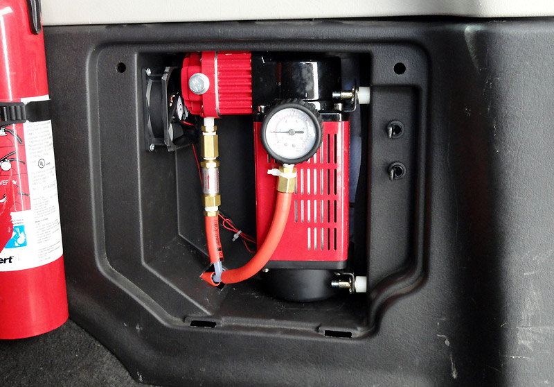
Standard MV-50 with a pressure gauge and one way valve. From here the line runs into the fender and below the vehicle.
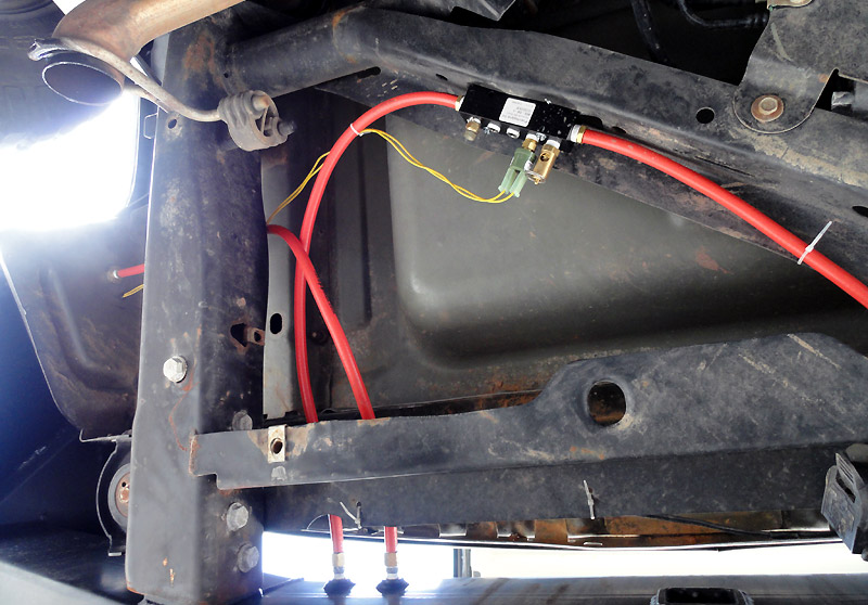
Under the vehicle, the line from the compressor comes in at the left of this image through a bulkhead fitting. The line goes to the tank in my rear bumper. From there it comes out to the manifold (with BOV & PS). From the manifold it runs right (out of the picture) to a quick connect mounted on the back bumper.
Overall, pretty simple.