Barlowrs Expedition Tacoma Build

john101477

Photographer in the Wild
I am not a member of the TW site but had to go over and look for sh ts and giggles. Lots of pavement pounders. I noticed a lot of favoritism instead of going by what the truck is equiped. Such as the 3rd group. Otismokie has that whole group hands down. not even close to a contest. A couple of near stock tacos with a lift and some meats is nothing to get excited about.
 

barlowrs

Explorer
Yep, that's precisely why I like Expo over TW. The other truck was nice too, but Barlowrs takes the cake hands down. I don't want to bash TW but... :coffee:


Bawlowrs truck is by far the cleanest, most well built I've ever seen anywhere. :Wow1:

haha yeah, the contest is really funny, essentially the finalist (I am still in, but just took 2nd in the last poll) is a mix of very nice built trucks (like Freeze for example) and other with 6" DB lifts sitting on shiny chrome wheels..its pretty funny! haha

Thanks, but in all Honesty, I think FREEZE is still ahead of me, his rig is nice! and of course, TACODOC was my inspiration for even getting the build going, so there are some great ones out there.
 
Last edited:

maxama10

Welcome to Nevadafornia
haha yeah, the contest is really funny, essentially the finalist (I am still in, but just took 2nd in the last poll) is a mix of very nice built trucks (like Freeze for example) and other with 6" DB lifts sitting on shiny chrome wheels..its pretty funny! haha

Thanks, but in all Honesty, I think FREEZE is still ahead of me, his rig is nice! and of course, DOCTACO was my inspiration for even getting the build going, so there are some great ones out there.

Oh don't get me wrong, I've drooled over their trucks too. The lift, bumpers, tires, snorkel and all that on your truck are great, but the little details are what makes your truck awesome. The radio install, mic jack, the toyota grill logo, custom things like that are sweet! I wish I had the competence to pull off stuff like that! :sombrero:
 

barlowrs

Explorer
Bud Built Skid Install with All-Pro Bumper (2nd Gen Taco)

Specific Thread (Comment Here): http://www.expeditionportal.com/forum/showthread.php?p=703301#post703301

Well after beating the crap out of my cross member and other underbelly parts, I figure its time to protect my girls belly…time for more armor! (My ½ ton truck is now pushing several tons with all the armor..haha).

As far as skids go, budbuilt is one of the best, and that is what I chose. These things are beautifully built and fit like a dream. Every hole lined up and there was no issues with the craftsmanship. I did however, run into one problem, and that is going to be the main focus of this write-up: The skids do not play nice with an all-pro bumper.

I know many people are running an all-pro plate bumper like me, and many people have often wondered if the bud built skid kit would fit. The short answer is yes, it does, however, it does require some modification to both the skid and the bumper. So here we go:

First things first, some paint. Because these are skids and I intend to use them as such, I chose standard old flat black rustolium. This is very easy to touch up after scraping the hell out of them on a rocky trip (this is what all my armor is painted with). The skids come VERY clean, I didn’t get a picture, but honesty, it looked like they polished them…they were sexy. Standard paint procedures here though, scuff them up with some sand paper or scotch pad, clean with acetone, and pile on the layers of paint.

IMG_3109.jpg


IMG_3110.jpg

IMG_3111.jpg


Once they are painted, its time to get to work. Start with the forward skid, this is where you will run into issues with the all-pro bumper. The skid utilizes the stock skid supports. Unfortunately, when my allpro bumper is mounted in the correct position, it is tight against the bottom of these supports; therefore there is no clearance for the skid to mount (this is also why a stock skid will not work with the allpro bumper:

(Sorry for the horrible picture):
IMG_3116.jpg


Luckily, the allpro bumpers bottom two bolts are located on the outside of where the skid mounts, so it is possible to trim the bottom lip off the bumper, but still use the lower two bolts. A quick pass with a plasma, and you are good to go (you can see what I mean below):

IMG_3123.jpg


IMG_3119.jpg


Now, this allows for the proper clearance between the bottom of the bumper and the skids, however, the skid itself still needs to be modified. When the skit is mounted, you can see that the front lip is not bent at a 90 deg (does not go up vertically) but instead sticks out forward a bit:

IMG_3117.jpg


Because the allpro bumper has a vertical support right at this location, the front lip must be trimmed to allow the bumper to mount properly. Once again, a quick pass with a plasma and you are good:

IMG_3118.jpg


Once this is complete, the bumper and skids bolt right up as they should. The rest of the install on the skids is very strait forward, and once again, because everything is manufactured so well, everything lines up perfectly making it very hassle free. Budbuilt already has a very good write-up on installing the skids so I will not get into all that.

Once they are all bolted up, here is the final product:

IMG_3122.jpg


IMG_3124.jpg


If you have any questions, feel free to hit me up.
 

barlowrs

Explorer
Garmin 60CSx Mount

Specific Thread (Comment Here): http://www.expeditionportal.com/forum/showthread.php?p=707973#post707973

OK first off, I want to give credit for this one, as I cannot take any credit. This idea was previously done by “DblD” in this thread: http://www.tacomaworld.com/forum/2nd-gen-tacomas/93807-ram-gps-mount.html

I really like his idea, so I stole it and took a few steps further. So, on to the write-up:

The Parts needed:
RAM Mount Garmin 60CSx Astro Cradle RAM-HOL-GA12U Model: RAM-HOL-GA12U
RAM Mount Diamond Plate with 1 inch Ball RAM-B-238U Model: RAM-B-238U
RAM Mount 0.25 inch NPT Thread with Single 1 inch Ball Model: RAM-B-218-1U
RAM Mount Short Arm B-Socket RAM-B-201U-A Model: RAM-B-201U-A
Garmin Cigarette Lighter Adapter Model: 010-10085-00
7/16 Fine Thread Bolt or threaded Rod
6 mm metric tap
6mm metric bolt or threaded rod

Steps:
First thing was to make the ballmount that interfaces with the trucks “ohh $hit” handle. This is where me and DblDs methods were a bit different. The threads that the ballmount comes with is 7/16 fine thread. I took a small threaded rod, cut it to length (about ¾” long) so that it will thread in and sit flush inside the ballmount. If you don’t have threaded rod, just cut the head off a bolt. Next, while it was still on the lathe, I drilled her right down the center and tapped it with a 6mm tap. DO NOT DRILL AND TAP ALL THE WAY THROUGH (make it a blind hole) otherwise your metric bolt will just thread into your mount and disappear before mating with the truck.
I then took my metric bolt (or threaded rod) chopped the head off and threaded it in so that it was about an inch or so sticking out:

IMG_3136.jpg


Add some locktite and you are good to go
Now, remove the a-pillar from the truck (very easy..two bolts) so that you can route the charger cable. While it is off, Drill a hole to run the wire out so that it can reach your GPS. Then re-install the a-pillar using the new ballmount in place of the lower “ohh $hit” handle mounting bolt location:
IMG_3131.jpg


In the picture above, you can see the charger wire going through the hole in the a-pillar.

Now, add the small arm and cradle and orient it how you like:

IMG_3132.jpg


Next was to wire it, you can easily keep the cigarette lighter plug and just use that, however, I wanted to hardwire mine into my auxiliary fuse block. To do I routed it into my engine bay through the grommet in the fire wall. I then cut the cig lighter plug off so that it is just the wires.

NOTE THAT A 1.5A FUSE IS CONTAINED IN THE CIG LIGHTER PLUG, SO YOU MUST FUSE IT EXTERNALLY IF YOU REMOVE THE PLUG

I then routed it to the fuse block, cut it to length and added standard ring terminals:

IMG_3134.jpg


All that is left is to plug it into the fuse block and fuse it. I used a 2A fuse (I will try to find a proper 1.5 “ fuse that will fit later, but 2A is the smallest I had laying around):

IMG_3135.jpg


And the final product, as seen from the driver’s seat:
IMG_3133.jpg
 

barlowrs

Explorer
OBA Install

Specific Thread (Comment Here): http://www.expeditionportal.com/forum/showthread.php?p=791342#post791342

Well after getting stuck over seas for work for a few weeks, I am back on schedule with my compressor install. So, here it is, hope it helps some people or give them some inspiration.
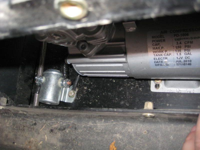
My plan was to have a compressor that could fill tires, blow out filters, etc, while at the same time, run some basic air tools for trail. I wish I could fit a york or belt driven compressor, but if you have ever looked inside the engine bay of one of these V6 tacos, that was clearly not an option. I researched a lot, and came to the conclusion that the PD-1006 compressor that is strapped onto the top of a Puma assembly was the best option. Here are the stats for the compressor:

¾ HP Running
1 HP Peak
3.4 CFM (not bad for a 12V compressor)
135PSI Working pressure
150PSI Max Pressure

In addition, here is a list of some of the other toys that go along with it:

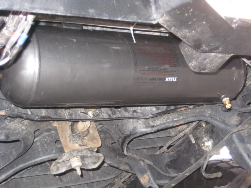
2.5 gallon Viar Tank (yes the puma came with a tank, but it was too small for my liking)
90 PSI On / 120PSI Off Pressure Swtich
140 PSI Blow Off
18” Steel Leader Hose
PA61A Load Genie Unloader/Check Valve
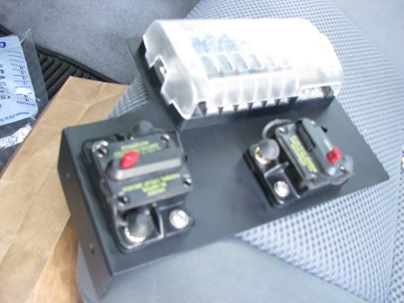
80A Resetable Water Proof Breaker
100 A Relay
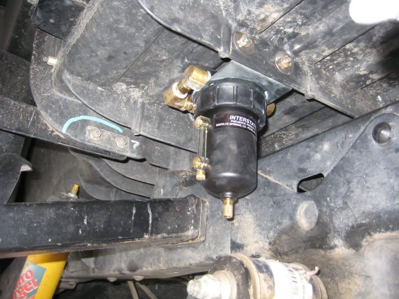
Interstate Metal encased water separator
75 ft of Nylon Tubing
7 port manafold
A LOT of compression fittings and other fittings
A lot of 4 AWG Wire

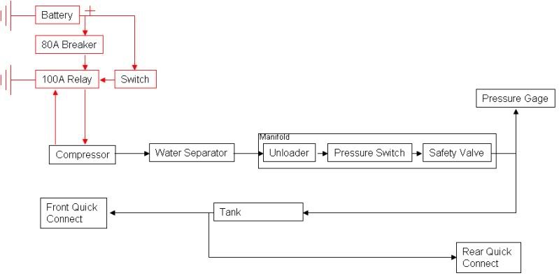
Hmm, there is probably a bunch of other stuff, but that is the basics….The scheamit I ended up coming up with went something like this. (Red is Electrical, Black is Air):

schematic.jpg


So…now it came time to mount it all. I wanted the compressor out of the elements best I could, but under the hood posed a few problems, first of all, it is very hot there, and heat is bad for compressors. Also, as we already established there is not much room, and this compressor is not a small one by any means. I thought about under the rig, but that is to exposed to the elements. Finally I fount a nice solution. Behind door number 1!

IMG_3453.jpg


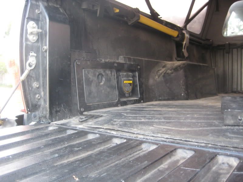
First thing I had to do was relocate the factory 120V plug. I do use this a lot, so I didn’t want to just get rid of it. Instead I made a harness and extended it to the other side of my bed.

IMG_3284.jpg


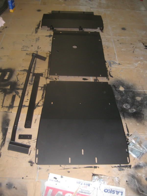
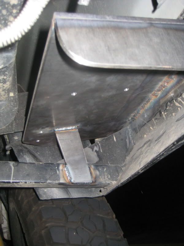
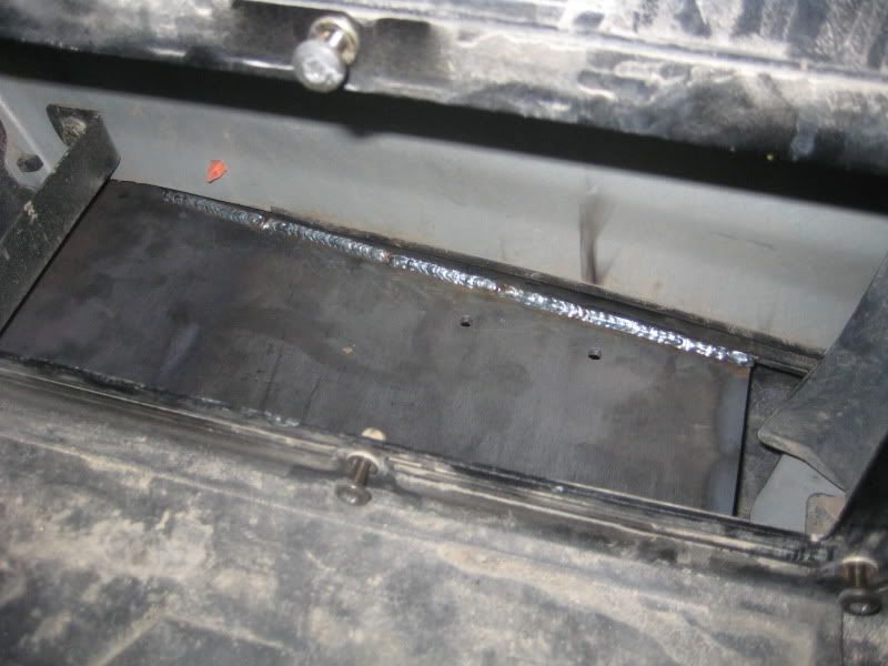
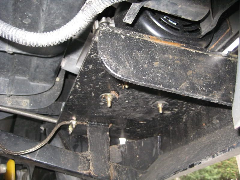
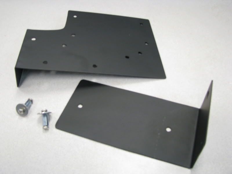
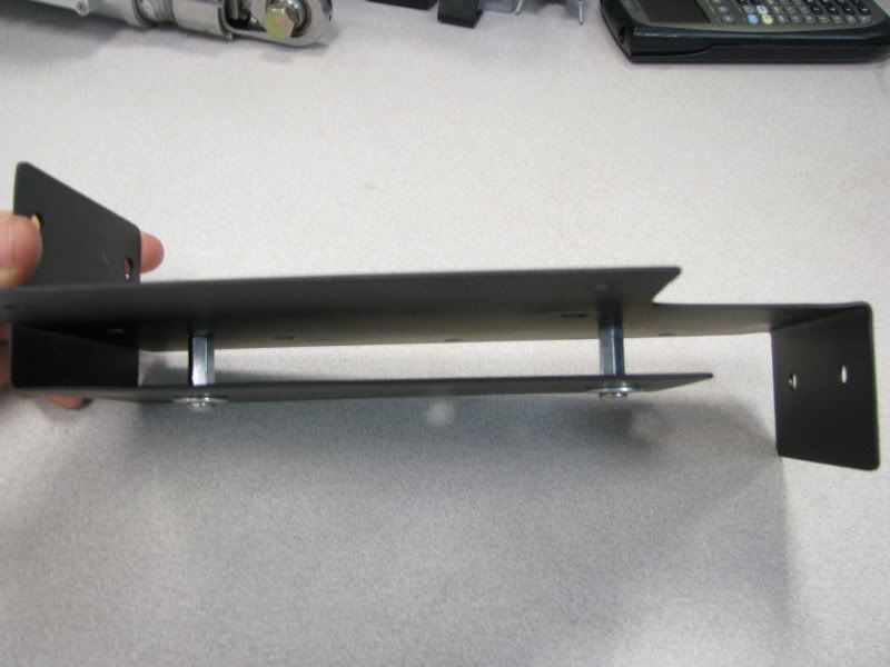
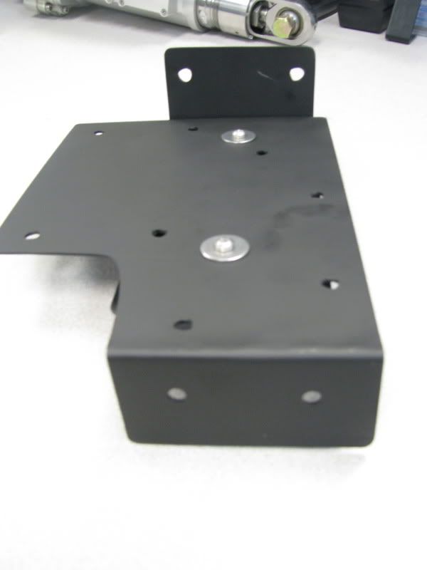
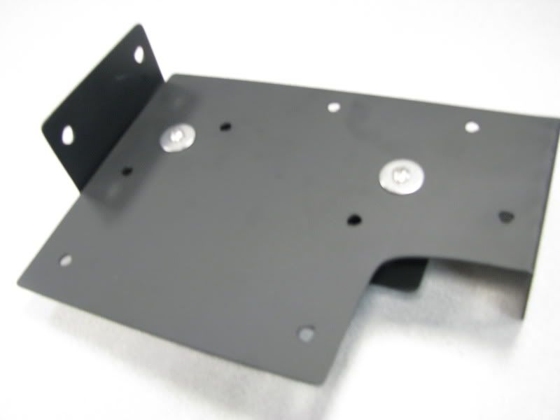
That left me a nice opening to play with. Because I have the CBI rear bumper, I have a large opening behind the cubby hole, and a lot of steel to weld to. I created a little shelf that welds directly to the bumper. Because this compressor is pretty hefty, I needed the shelf to be strong since it is cantilevered off the bumper, I used ¼” Plate and added some nice gussets for bracing. Here are few pics of the shelf and the bracing.

IMG_3287.jpg


IMG_3285.jpg


This also give me a nice place to mount the 100A relay. Here you can see the relay. In addition I added a separate ground strap..just to be safe. Non proper grounding is a bad thing.

IMG_3449.jpg


IMG_3451.jpg


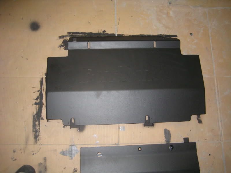
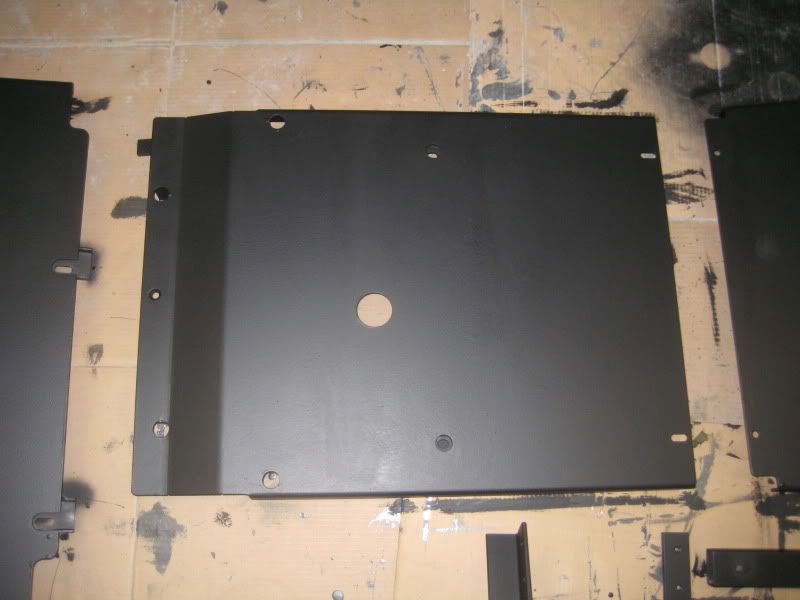
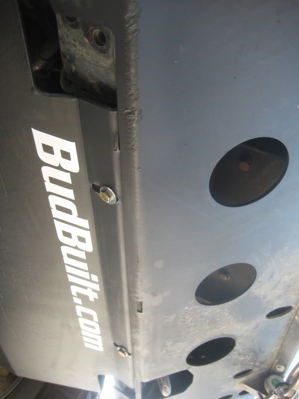
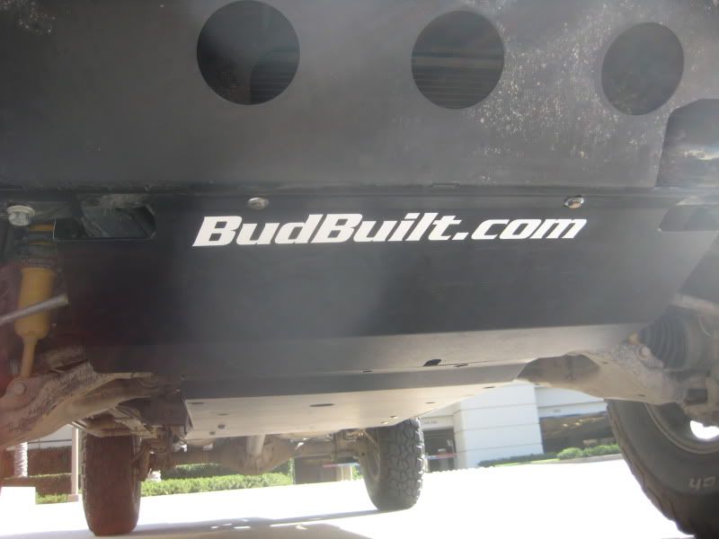
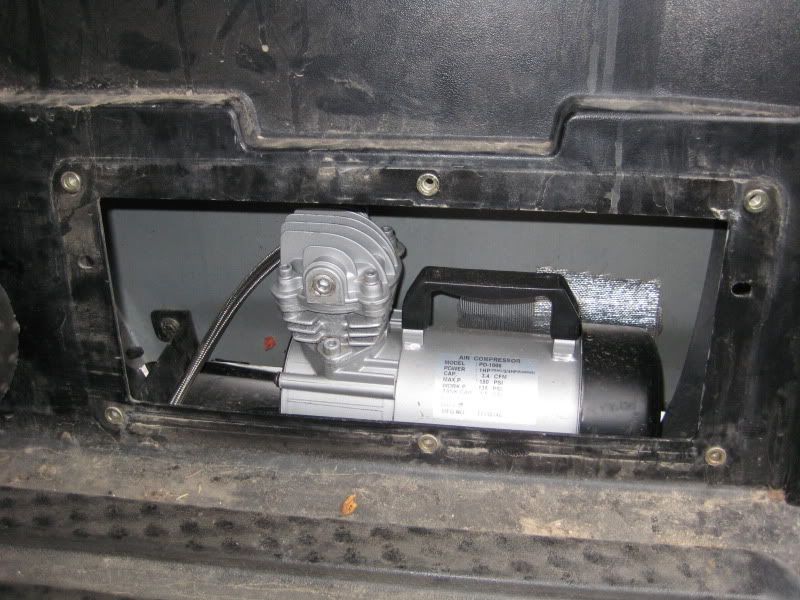
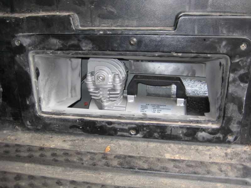
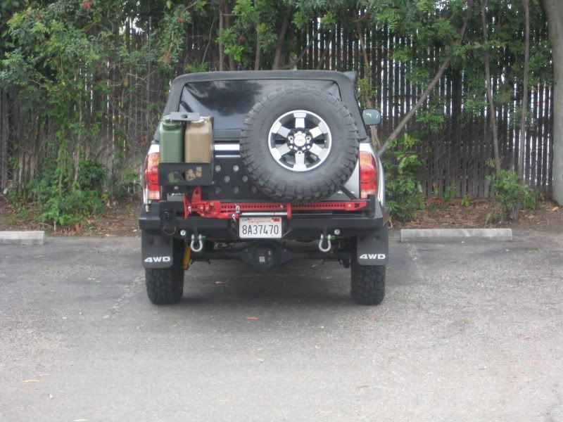
Next was to mount the compressor and trim the cubby to fit around it. The cubby provides some nice protection for the compressor while also proving enough space for her to breath. I also added some fiberglass heat shielding behind it so my body paint doesn’t start to melt on the outside. With the cover closed, you would never know I had a compressor there (the first pic in the post is with the compressor already mounted….didn’t see it did you!?)

IMG_3448.jpg


Cubby Mounted:

IMG_3452.jpg


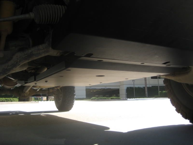
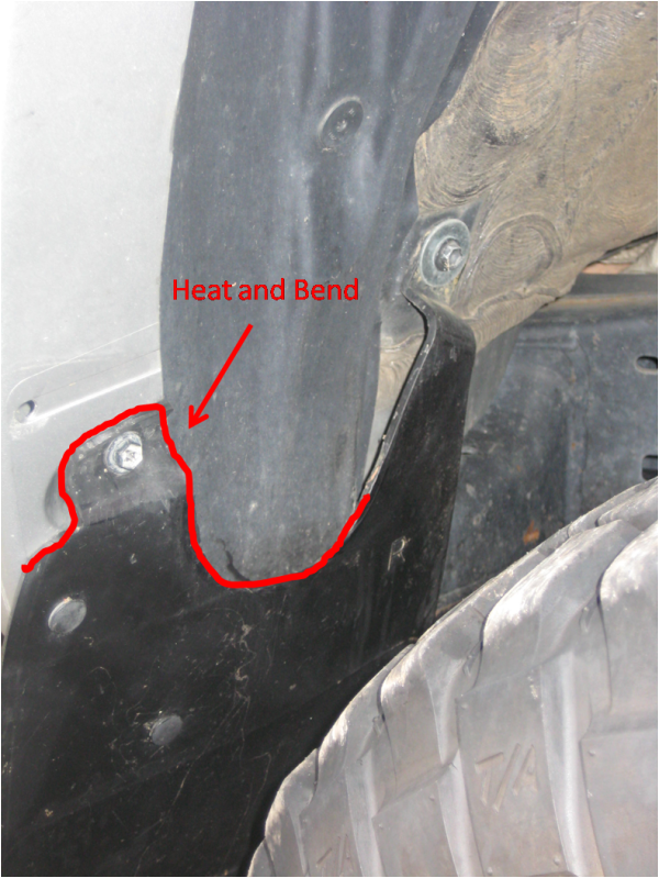
Now for all the accessories. The water filter is mounted right above my rear shackle, This makes it accessible to drain, but protects it because the suspension would hit before any rocks hit it. I also opted for a metal encased filter to be safe.

IMG_3450.jpg


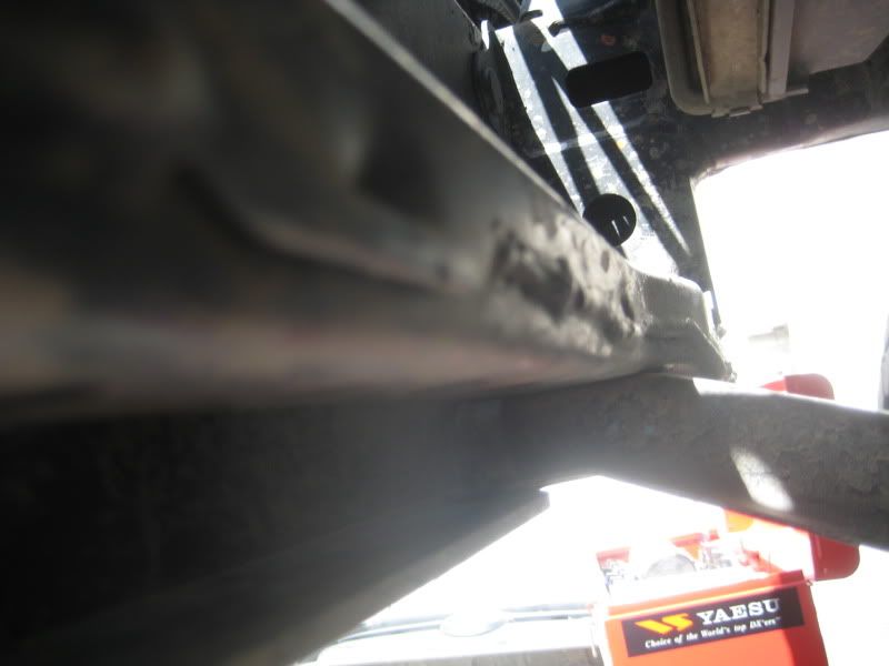
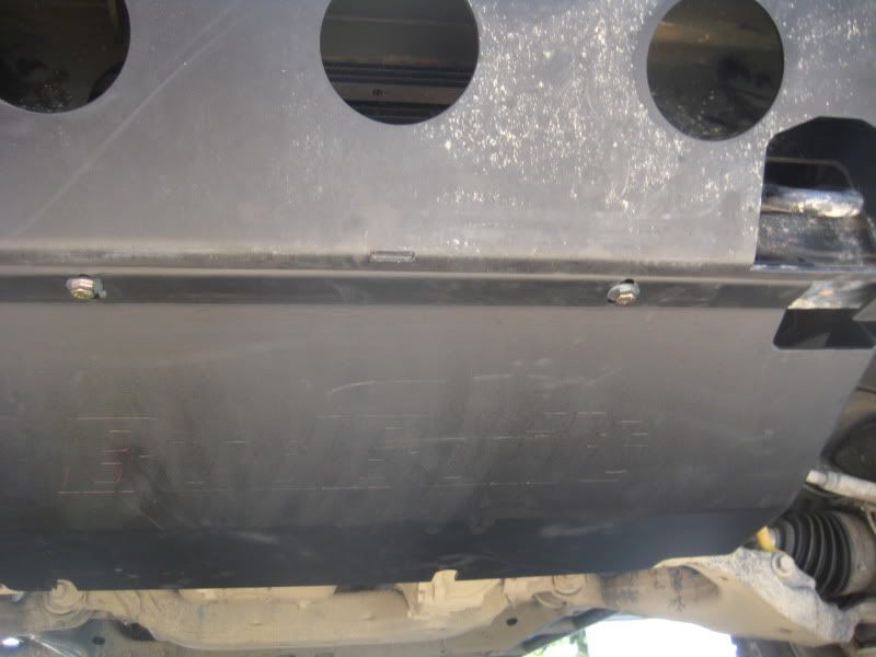
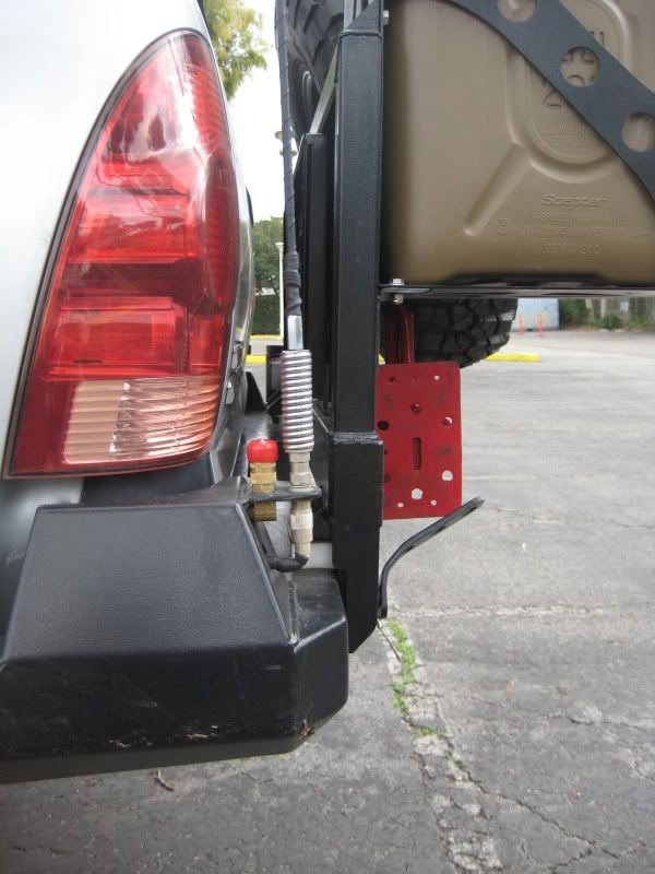
The tank is mounted right in front of my rear bumper. It is just the perfect height to not hang below the bumper (even the drain cock).

IMG_3457.jpg


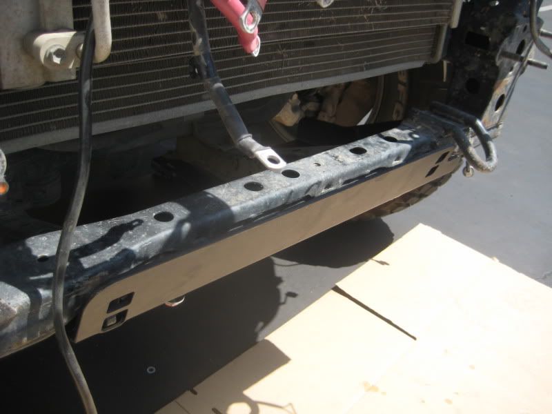
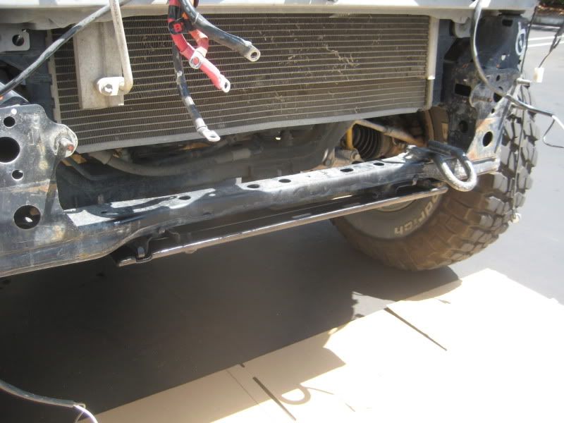
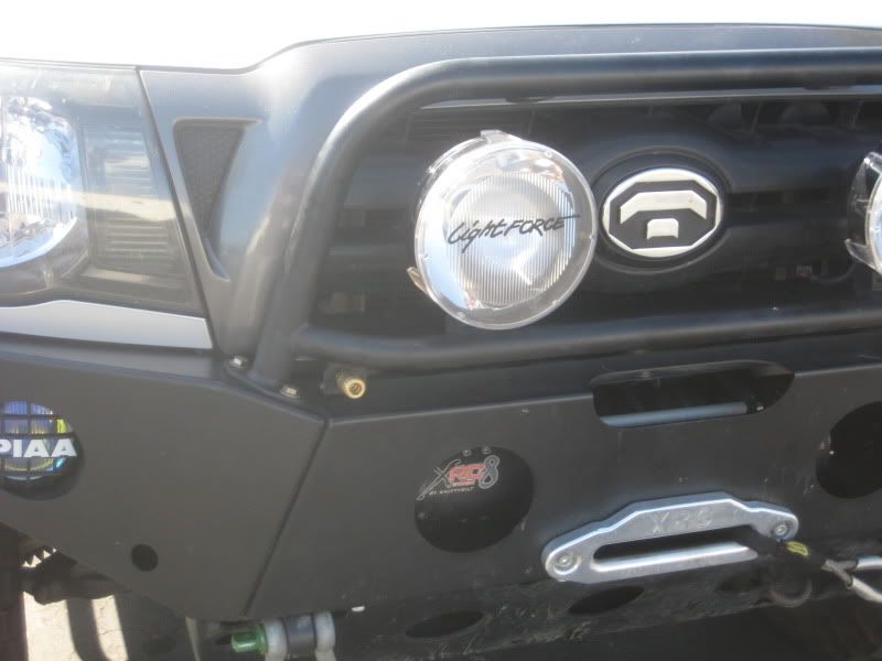
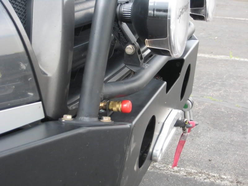
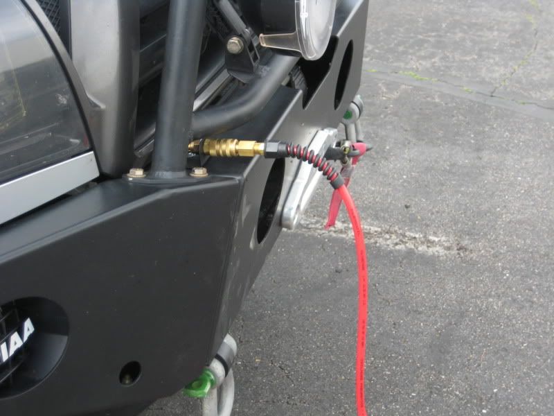
I then decided to go with two quick connects, one up front and one out back. I made a little bracket for the front one and bolted it to my Allpro bumper

IMG_3283.jpg


IMG_3460.jpg

IMG_3461.jpg


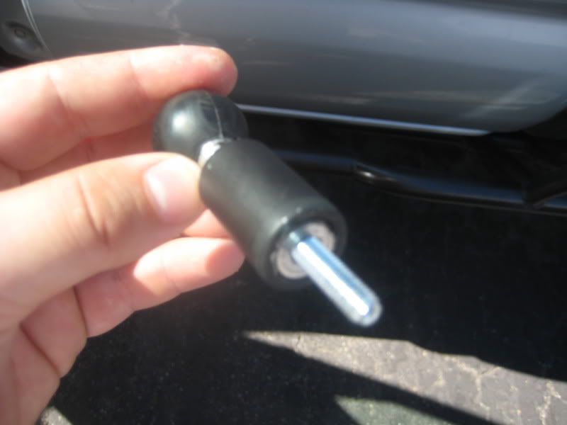
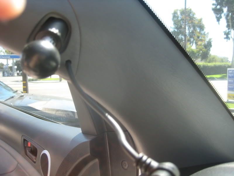
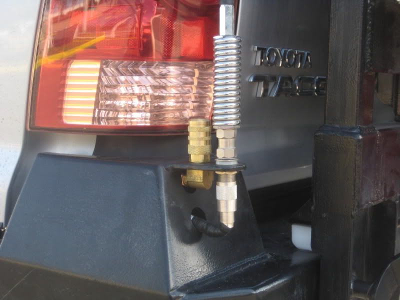
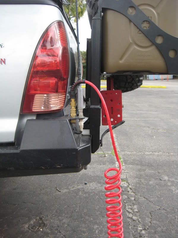
For the rear, I decided to mount it vertically off of the antenna tab on the CBI bumper. Mounting it vertically is a bit risky as moisture could flow down into the system, but I have some nice covers grabbed from work.

IMG_3280.jpg


IMG_3458.jpg


IMG_3459.jpg


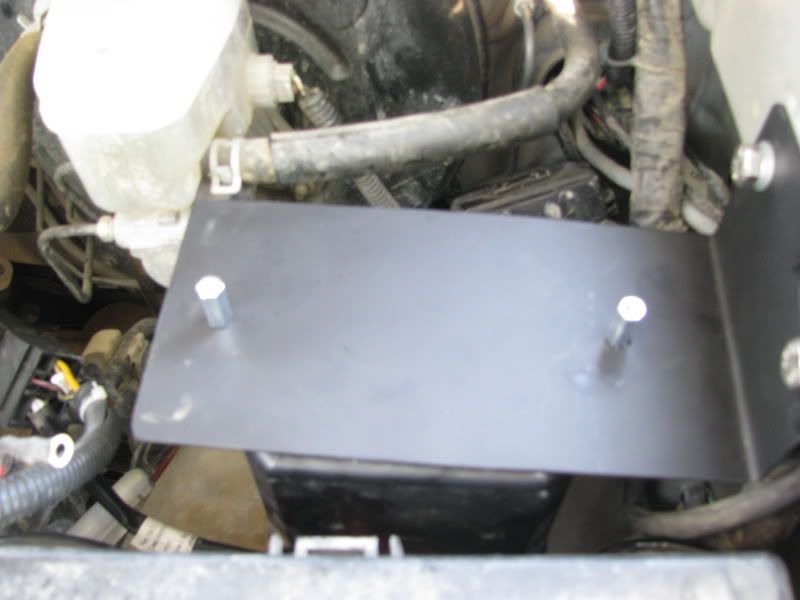
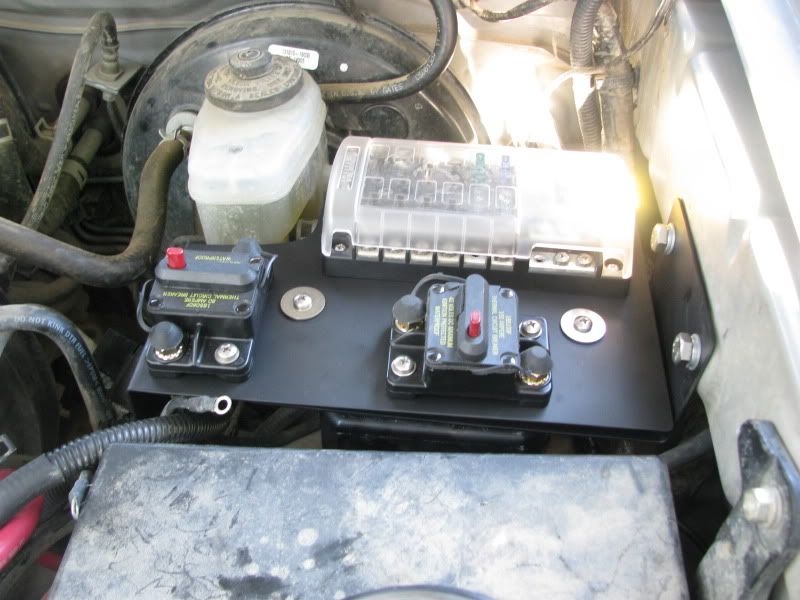
The wiring will be in another write-up as I revamped my aux fuse block mount to make room. That should be up in a week or two.


Thanks
 

barlowrs

Explorer
Aux Fuse Block V-2.0

Well, as some of you may know I have recently installed my OBA system ( OBA Install). This has required me to add a 80A breaker to my arsenal. While doing this, I decided to upgrade my 100 Fuse that was wired to my Aux fuse block to a resettable breaker as well. The last thing I want is to be out somewhere and blow the fuse and not have a spare. The resettable breaker allows me to not have to carry spares (those fuses are pretty pricy too). So this led to a re-design of my under hood mount…let’s call this V 2.0.

While my original mount worked well (Aux Fuse Block V-1.0), I did have one complaint after having it for a while. Because my winch solenoid was mounted to the bottom, it made it very difficult to remove to gain access to the firewall grommet, or to remove for other reasons. In my original design, I never thought I would be removing it, but over the past year or so, I have had to do this multiple times, and it proved to be a pain, so my redesign had to have the following requirements:

- Easy to remove the fuse block
- Room for Fuse block and 2 breakers (100A and 80A)
- Still maintain my winch solenoids
- Room for at least 2 light relays
-
After messing around with a few ideas, this is what I came up with…now out with the old and in with the new!

The new design is two parts, the lower shelf is smaller, so it can stay permanently mounted and still five me good access to the firewall, etc. This lower shelf is where my solenoid mounts too. This is hard mounted to the truck.

The upper shelf which holds the relays, fuse block and breakers is no longer bolted to the truck itself, but rather the lower shelf through the use of 2 bolts that get bolted into stanchions that stay on the lower shelf. This allows me to EASILY (2 bolts) remove the upper shelf, and the stanchions stay in place such that I don’t even have to mess with nuts on the back side.

Like my original, this is built with 18 gage stainless steel.

Here you can see the two parts and how they fit together:
IMG_1495.jpg


IMG_1497.jpg


IMG_1498.jpg


IMG_1496.jpg


Now, time to mount under the hood. The small shelf gets hard mounted to the fender (same as original design) with the winch solenoid mounted below it. Here you can also see the box that contains my winch solenoid mounted.
IMG_1500.jpg


The upper shelf gets equipped with the fuse block and breakers. (The relays get mounted to the two holes on the vertical side once it is mounted in the engine bay).

IMG_1499.jpg


Lastly, it is simply bolting the two bolts in place to mount the upper shelf to the lower shelf and there you have it.
IMG_1501.jpg


I think this should serve my purposes well.
 

barlowrs

Explorer
1st Gen Mudflap Install

OK, well if you are like me running a high clearance bumper, you have probably removed your rear mud flaps, since you have to cut them off for the bumper. I still wanted to run mud flaps, as I kept getting rock chips on my nice high class rustoleum paint job, and I suppose because it’s also the law here, so I decided to fit a pair of 1st get flaps. While I was at it, I also decided to try to fit up the 1st gen front flaps as well, these are not nearly as stiff as the 2nd gen flaps, so they do not get ripped off. So here we go.

Front Flaps:

The front flaps required a little trimming a little drilling and a little heat+bending, but overall they fit pretty well.

First just mock them up where you want them, the inner bolt hole actually lines up pretty well with an existing bolt on our trucks, so I based it off of that. Once you have the general idea of where you want them, start trimming. In the picture below you can see where I trimmed (the red lines). I also decided to heat the plastic up and bend it to allow me to use another exiting hole.

FrontTrim.png


Once you have it trimmed and fitted where you want, drill holes so that it will bolt into existing holes. I was able to get 2 bolts and 2 clips per side, it is pretty sturdy.


IMG_3519.jpg


Rear Flaps:

I cannot take credit for this, I got the idea from TACODOC, but here is the way I did mine. These took a bit more caressing, as you have to trim the bracket. Basically, once again, mock it up how you want it (cardboard works very well) and cut out the profile of the bumper from the flap. Once you have it where you want, hold the mounting bracket up and see what needs to be trimmed there. I ended up doing a lot of hacking on the bracket, but it is still pretty sturdy. Again, you can see where I cut (red lines) in the picture below.

RearTrim.png


Once you get the hanger and flap looking how you want in the correct spot, it’s just a matter of drilling some holes, using self tapping screws , and your good to go. I also drilled a third mounting hold on the flap itself (see pic above) to provide more support to the top of the flap.

IMG_3521.jpg


And here is the final result, no more pesky rock chips, now only nice rock scratches haha.

IMG_3518.jpg


IMG_3517.jpg
 

4RunAmok

Explorer
Not having front flaps on mine has caused havok on the powder coating on my sliders. I have some rust forming on them now.

Found a cool product for neutralizing rust on metal, immediately readying it for paint... found here. I'll be picking up some of these and painting the effected spots with Rustoleum.
 

Forum statistics

Threads
185,798
Messages
2,878,296
Members
225,352
Latest member
ritabooke
Top