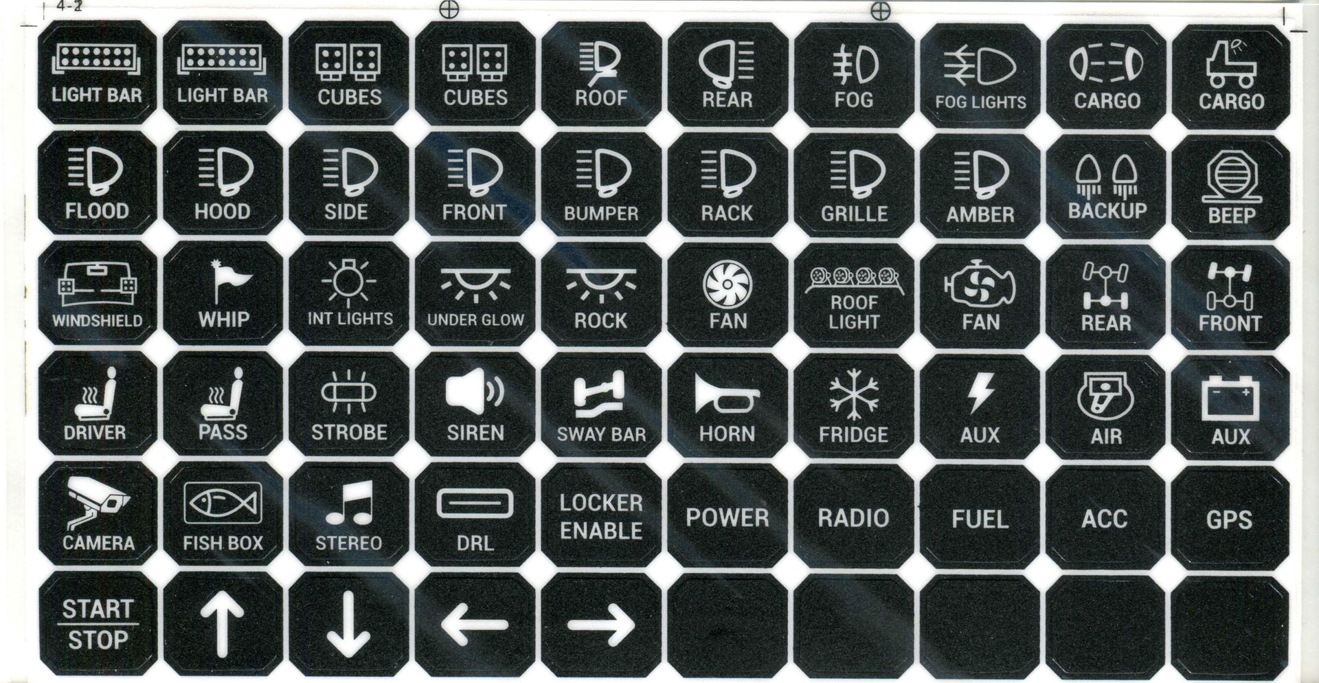
Auxbeam’s RA80 X2 Dual Panel Switch System in a Camping/Overland Vehicle
Part 1 - Overland Wiring Options
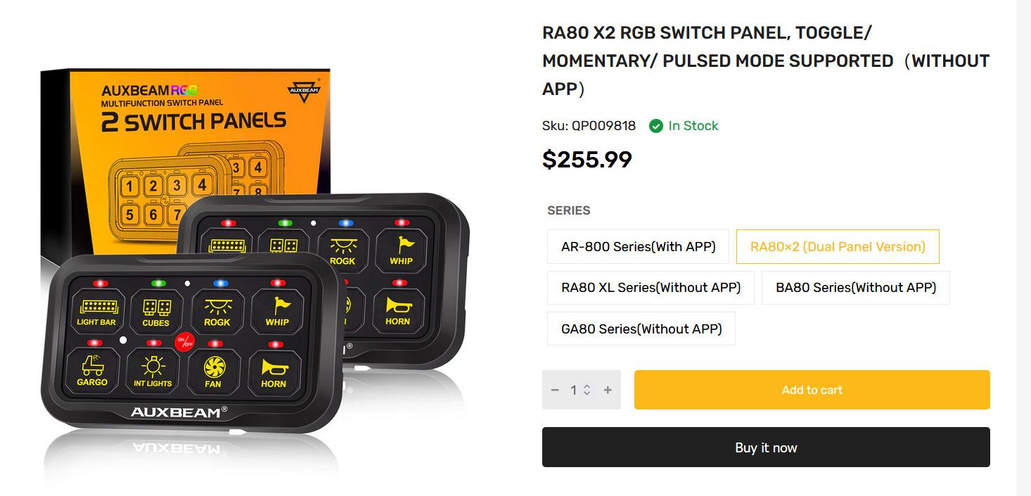
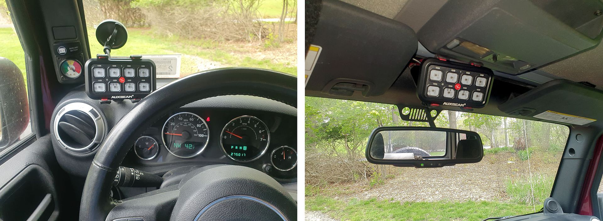
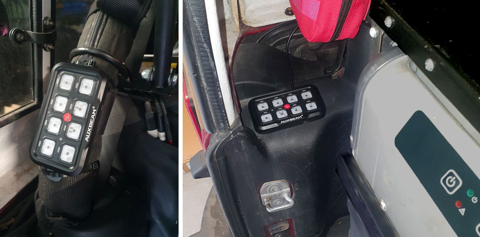
Auxbeam’s RA80 X2 8-gang dual switch panel system can be very useful for a vehicle configured for camping and overlanding - one switch panel can go within the driver's reach for accessories like driving lights, and the second panel can go in the back to be easily accessible at the camp site (
https://auxbeam.com/products/qp009818).
Using dual panels to control driving and campsite accessories does bring up additional wiring considerations. Normally, the system would be powered by a switched circuit in the vehicle and therefore only powered when the ignition is switched on, but it is not a good idea to require the ignition to be switched on whenever accessories controlled by the switch panel need to be used at the campsite - at best, it's inconvenient and at worst leaving the ignition switched on at the campsite could result in the battery being drained. This article will cover wiring considerations and some installation details for a typical camping/overland vehicle to avoid unnecessary battery drain at the campsite.
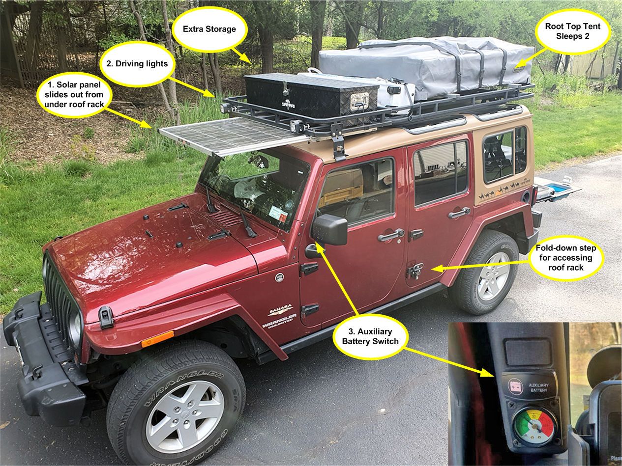
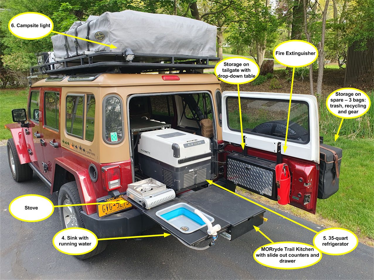
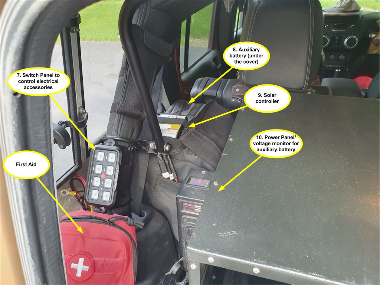
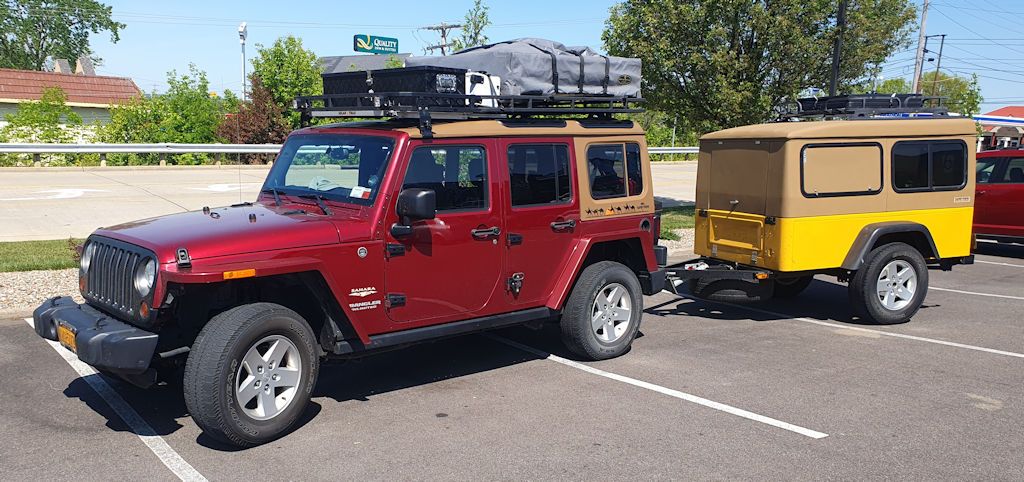
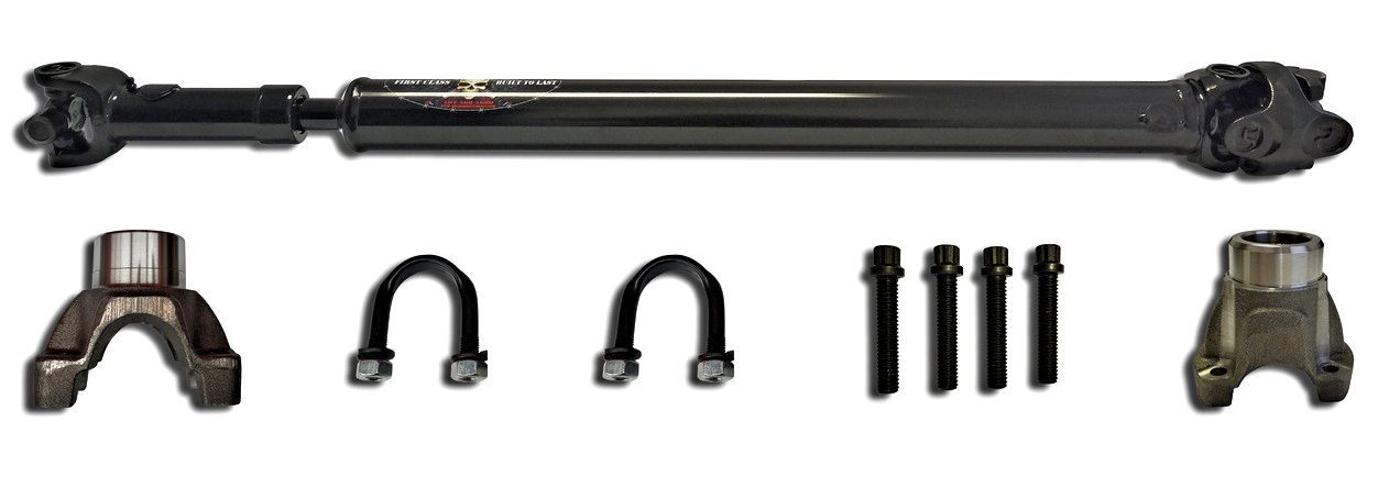
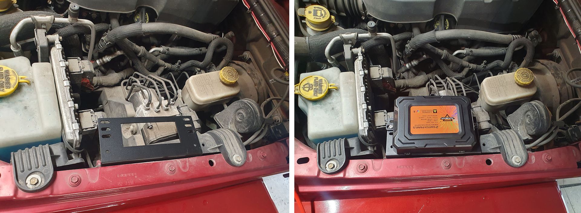
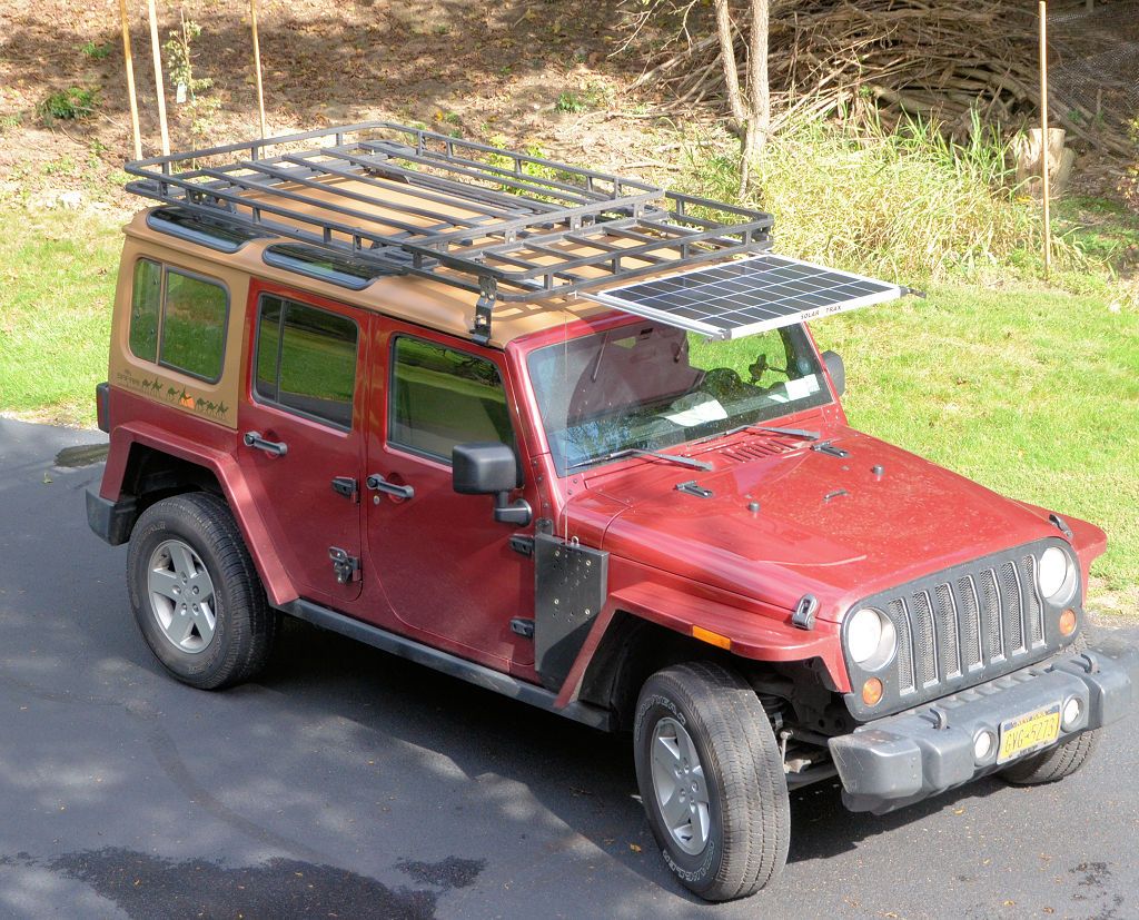
The vehicle being used for this article is a 2013 Jeep Wrangler Unlimited. In front it has Auxbeam driving lights mounted on the roof rack and in the cargo area a MORryde Trail Kitchen is installed. One of the switch panels will be mounted up front near the driver and the second will be mounted in the back by the Trail Kitchen.
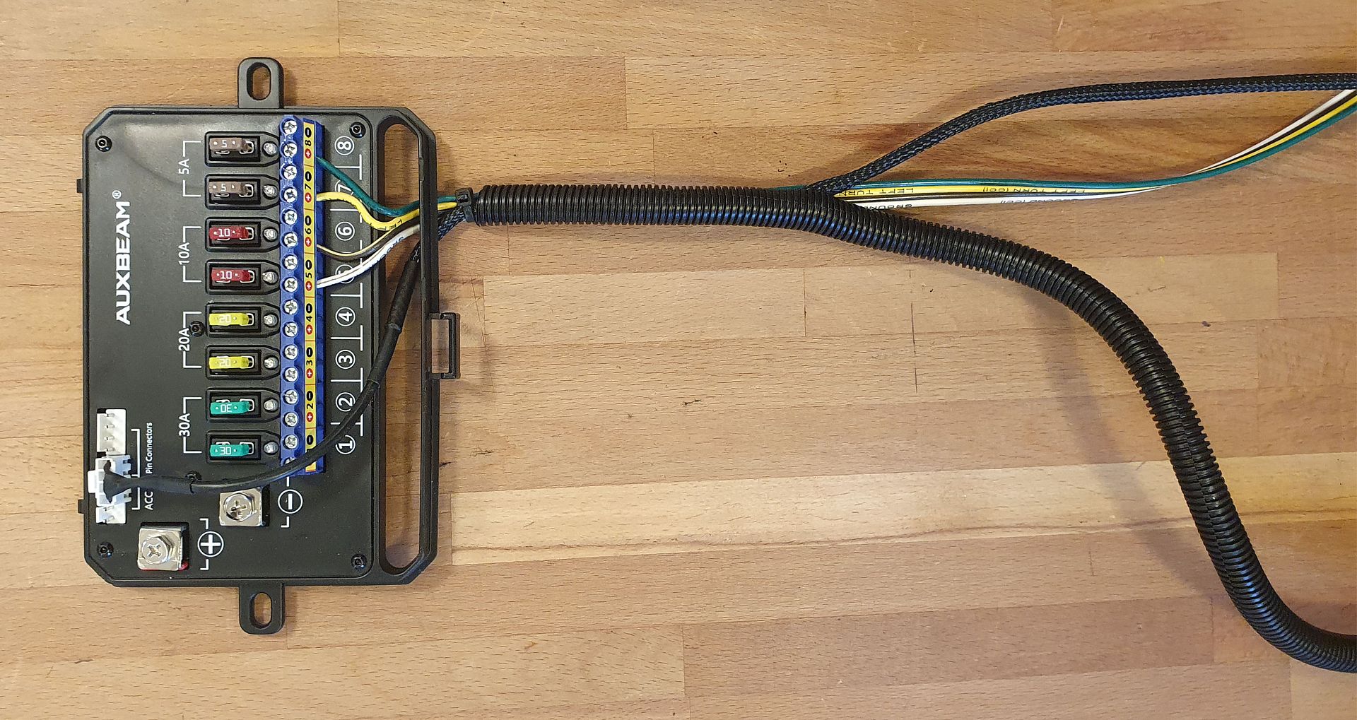
The first thing to know in planning your installation is that the two switch panels work in parallel - there are 8 circuits in the RA80 X2 control box and each panel has 8 switches. Switch 1 on both panels controls circuit 1 in the control box, so if driving lights are connected to circuit 1, switch 1 on either panel with operate those lights. You have 8 circuits for accessories, and all of those 8 circuits can be controlled from either panel.
Powering the RA80 X2 Control Box
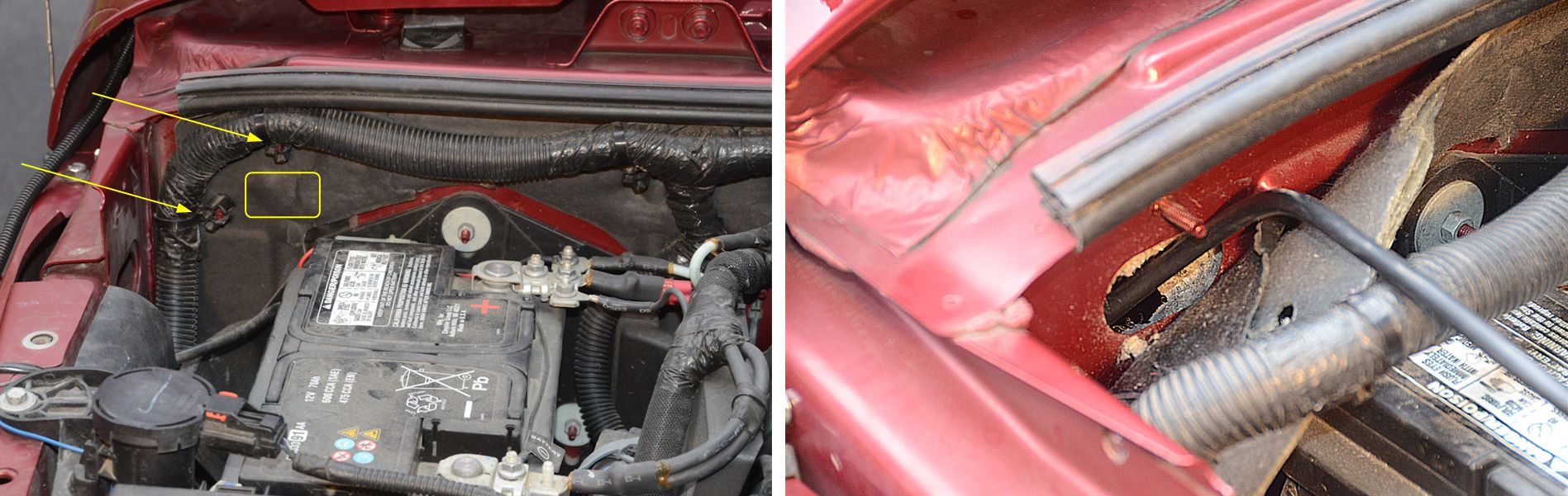
With a typical single switch panel system, it is normally recommended that the control box be powered by a switched circuit in the vehicle. A switched circuit is one that's powered on when the ignition switch is in the on position, and powered off when the ignition switch is off. Powering the panel with a switched circuit ensures that the switch system and its connected accessories won't drain the battery when the vehicle isn't running.
Considerations may be different for a dual switch panel system - if the second panel is mounted in the back of the vehicle for use at the campsite, for example to control campsite lights mounted to the roof rack, you wouldn't want to have the ignition switch on all the time at the campsite - you'd want the switch system to operate without the ignition switch having to be on. Let's review three wiring options...
Wiring Option 1 - Switched Circuit in Vehicle (Per Auxbeam Instructions)
The instructions recommend powering the control box from a switched circuit in the vehicle, which means that any accessories connected to the system will only be able to operate when the vehicle is running or the ignition switch is turned on. For accessories used when driving, like driving lights, that's not a problem, because the switched circuit will be on.
But if the second switch panel is used in the back of the vehicle to control campsite accessories, you would either have to have the vehicle running or have the ignition switch turned on at the campsite for those accessories to be used. Running the engine all the time probably isn't a good idea, and having the ignition switch turned on all the time at the campsite isn't the best idea either - the vehicle circuits that are powered when the ignition switch is on will be an unnecessary drain on the battery and could lead to a discharged battery overnight.
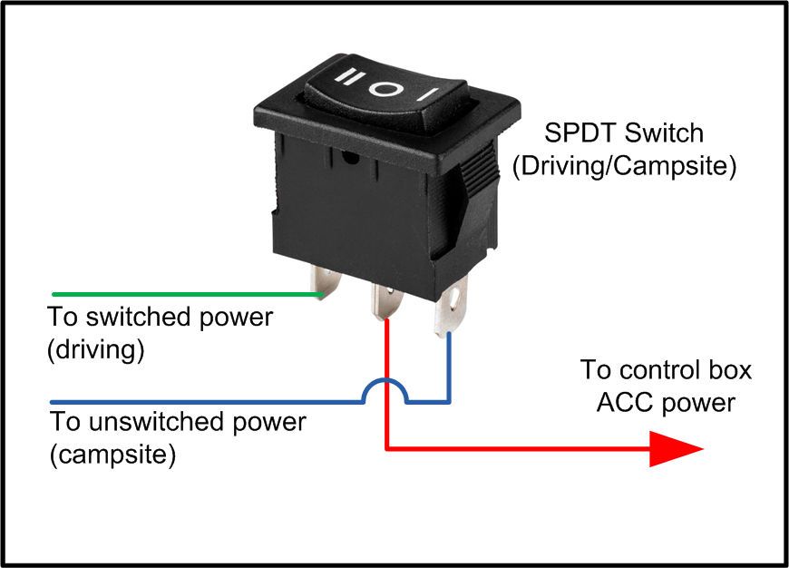
Wiring Option 2 - Driving/Campsite Switch
A way to use the switch system with the ignition switched off is to install a switch to control the power to the control box. In the "driving" position, the switch would power the control box from a switched circuit and in the "campsite" position, the switch would power the control box from an unswitched circuit. What’s good about this is for normal driving, any accessories controlled by the system will be powered off when the vehicle is not running, so they can’t be left on accidentally and drain the battery. And at the camp site, accessories can be used without the need for the ignition switch to be on.
The switch is a single pole double throw (SPDT). Optionally it could be an SPDT Center Off switch, in which case the center position would cut all power to the control box off.
The benefit of using the switch system in "campsite mode" is that the vehicle circuits that are powered by the ignition switch being in the on position will not be powered, which eliminates some drain on the battery while sitting at the campsite. Typically, you wouldn't be using "driving accessories" at the campsite such as driving lights, you would only be using campsite accessories, perhaps LED campsite lights mounted to the roof rack, so power drain would be limited to just the campsite accessories plus the small power draw that the switch control box requires.
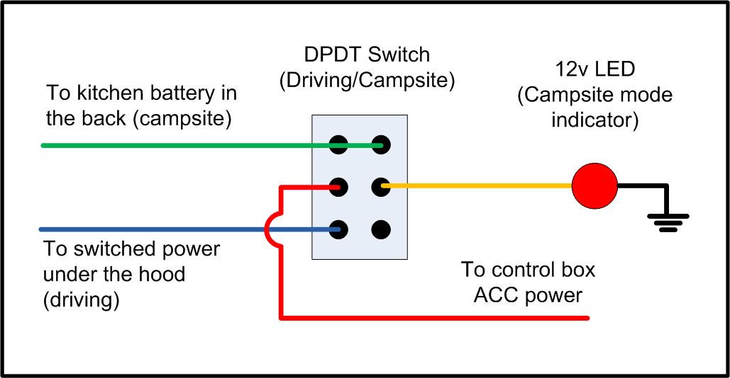
But forgetting to turn off campsite mode when you no longer need it could cause your vehicle battery to discharge, so it might be a good idea to have a reminder that the campsite mode is on. This can be done with a double pole double throw (DPDT) switch and a 12v LED indicator light; wired as per the next diagram, the LED will light whenever campsite mode is on and will serve as a reminder to turn off campsite mode when it is no longer needed.
The switch control box draws about 75ma. with both switch panels connected and all circuits turned on. That's a negligible drain on the main vehicle battery just for the control box, but to that the drain of the accessories switched on must be added. For example, if an accessory that draws 10 amps is to be switched on, it may not be a good idea to power that from the main vehicle battery when the vehicle isn't running - it may drain the battery past the point of being able to start the vehicle the next morning. Which leads us to the third option...
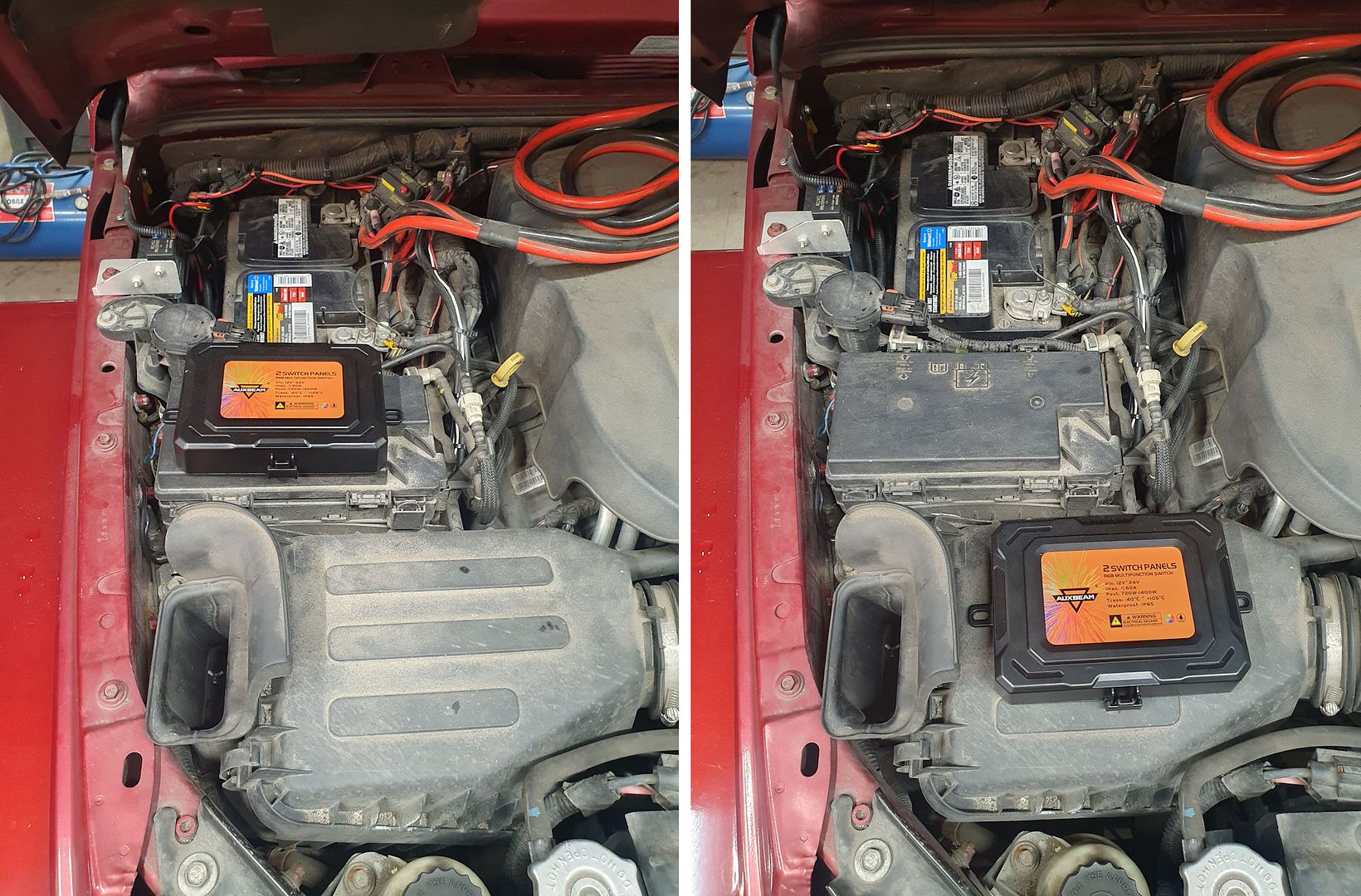
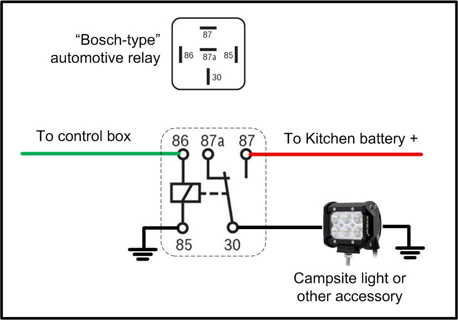
Wiring Option 3 - Vehicle with two batteries
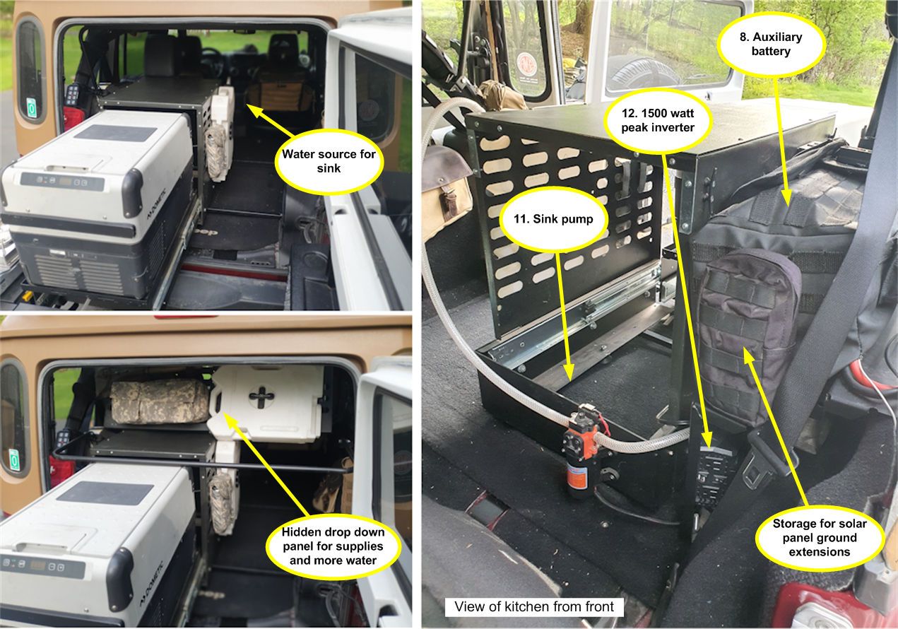
Our test Wrangler has two batteries - the standard vehicle battery up front, and a fridge/kitchen battery in the back. In this vehicle, we'll use the driving/campsite switch described above to power the switch control box, but the campsite accessories in the back can be powered either from the main vehicle battery or from the kitchen battery. Powering campsite accessories from the kitchen battery will greatly reduce the load on the main vehicle battery, ensuring that the main battery will have enough power to start the vehicle when it’s time to leave the campsite. More on this wiring later.
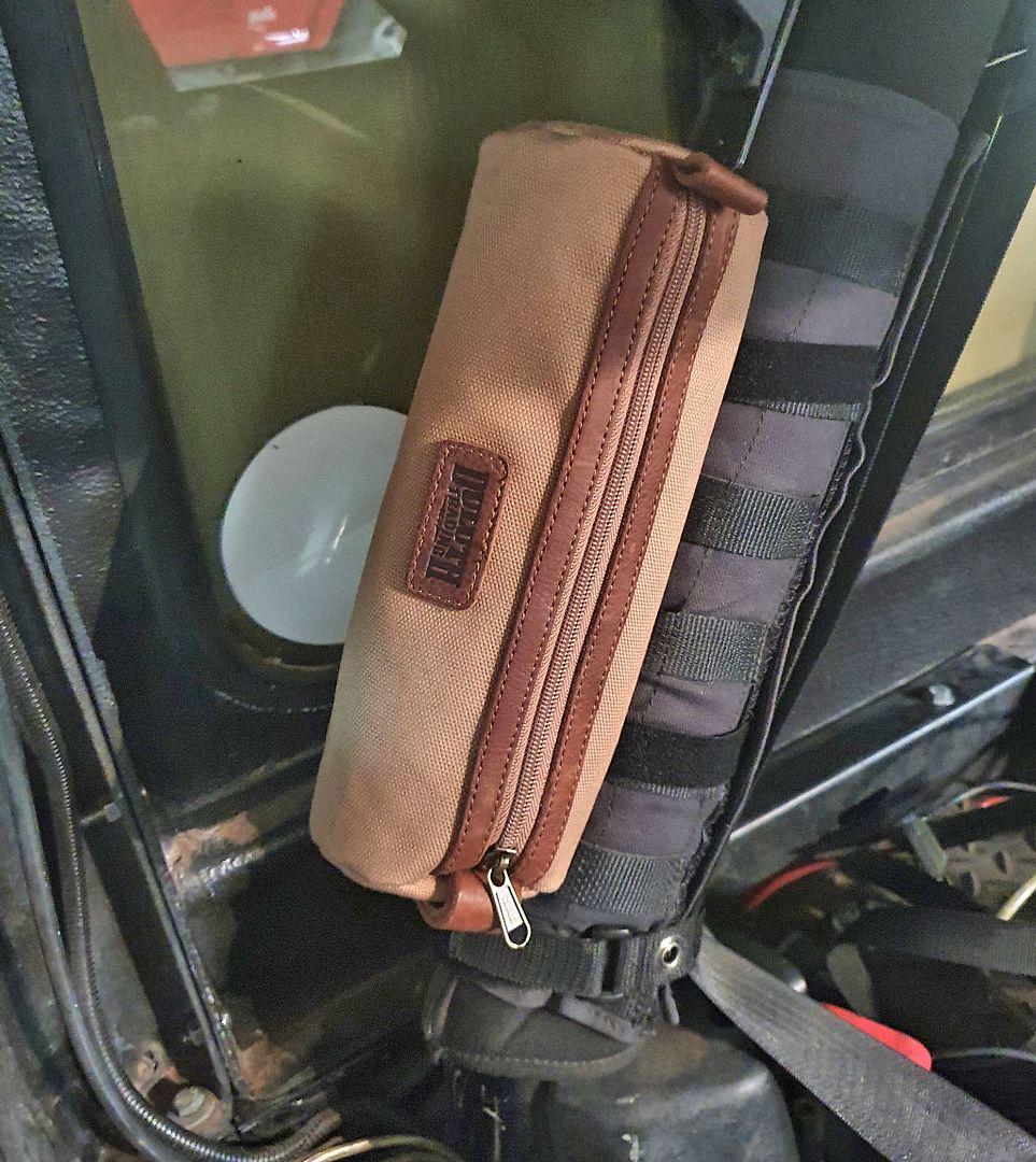
The test Wrangler has a refrigerator in the back that’s powered from the fridge/kitchen battery. Since the fridge typically is used from the moment food is loaded before an expedition until returning home, there’s no real need to control its power using the switch panels. The kitchen battery is mounted in the back right next to the fridge, and the fridge has a convenient power switch on its front panel, so it’s directly connected to the kitchen battery. Only accessories which will be turned on/turned off at the campsite will be controlled through the switch panel system.

")