pivoting frames and mounting campers

whatcharterboat

Supporting Sponsor, Overland Certified OC0018
I have a ton of cool atw pictures that have been posted over the past couple years, that are now gone. here today, gone tomorrow. This is not the first time it has happened here.

Hi Leon,

If you are referring to any pics I've posted up that are no longer ......... I don't think I have ever intentionally removed a pic. It would have just been me using up the 200 pic limit on my Flickr account which automatically removes the first pics in the account as you add more new ones. Then once I realize, I usually start another account. I think I have 4 accounts running now. Very sorry if that is the case. Happy to repost any that have been removed. I literally have thousands of pics.......and shoe boxes full of old photographs from the early Canter days waiting to be scanned at some point in the future. Just ask if one has disappeared and I'll get on to it.

BTW.....I am absolutely amazed that this thread has run to 30 pages.

Kind regards John.
 
Last edited:

EarthCruiser

Adventurer
Doug absolutely no harm done or need for the detailed response, although much appreciated. We thoughly enjoyed spending time with you, a worthwhile investment to say the least. As promised I will provide the A.D.R. drawing guidelines for this mounting option for anyone who requests them. I think we need to be clear that the key is in the “application” of this system.. With all due respect to fellow portal members, a little piece of knowledge can be a very dangerous thing.

We are just back “home” in Portland recovering from EXPO, which was a fantastic event. We have enjoyed the entire experience. On the way I got to visit some amazing spots, if you have not been Mesa Verde go.

Next for me is the Brisbane Truck Show in Australia. We’ll have an EarthCruiser at the Truck Show. Look forward to having a chat with portal members that can make it. It will be a great show.
 

SkiFreak

Crazy Person
As promised I will provide the A.D.R. drawing guidelines for this mounting option for anyone who requests them.
I believe that the Australian Design Rules (ADRs) being referred to here are from VSB6 - Heavy Vehicle Modifications.
If anyone is interested, the official link to these documents is here:
http://www.infrastructure.gov.au/roads/vehicle_regulation/bulletin/vsb_06.aspx

Spring mounts very similar to that used by EarthCruiser are pictured on page 14 of Section J.
 

mog

Kodiak Buckaroo
I believe that the Australian Design Rules (ADRs) being referred to here are from VSB6 - Heavy Vehicle Modifications.
If anyone is interested, the official link to these documents is here:
http://www.infrastructure.gov.au/roads/vehicle_regulation/bulletin/vsb_06.aspx

Spring mounts very similar to that used by EarthCruiser are pictured on page 14 of Section J.

WOW!! What a great resource! Thanks a bunch for posting that link. There are a lot of good ideas in those.
 

haven

Expedition Leader
http://www.billcaid.com/2010/1017ACamperConstruction20100921/TripMain.html

Bill Caid is a well-known Unimog enthusiast from southern California. Bill recently built a new, larger camper based on the Mercedes 1017A chassis. Bill used the Unimog style mount for the camper subframe. He rigidly mounted a crossmember just behind the rear axle, and added pivot points near the cab and at the rear of the frame. The result has a surprising amount of articulation. Lots of photos at the link above.
 

RoosterBooster

Observer
lots of great info in this thread ! :coffee:

i may throw "my" flexible body mount ideas into the pot;


over 10 years ago i modified my MDT boxtruck (IH 4900) for better rough-road capability:
phoca_thumb_l_PA061974.JPG

i shortened the box and added a sleeper in between cab and (living quarters) box
advantage;
- each section was individually mounted = frame was fairly free to flex.
disadvantage;
- complex and labor intense
- lots of walls = loss of valuable floorspace
- needed 2 rubber bellows to connect the 3 spaces = high potential leak risk

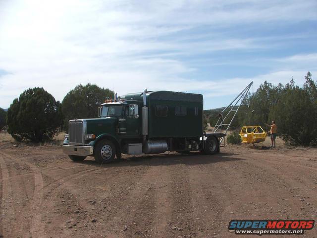
some 5 years ago i switched to a HDT (Pete379 semi converted to single rear axle RV)
aframe-crane1.jpg

i extended the factory cab/sleeper to 162" and mounted it on 4 air bags.
advantage:
- amazing smooth ride even on rough gravel roads
- from the front pivot cab mounts back the frame is completely free to flex
- very quiet; the air bags are excellent for isolating chassis noise & vibrations
disadvantage;
- very complex and labor intense
- very material intense; to locate the box and control the airbag travel i needed bumpstops (up and down) adjustable shock absorbers, panhard bar, self leveling valve, ...
- needs air ; the box needs "landing pads" on the frame as well as "drop legs" to support it when camping for extended time (air will bleed slowly even if you plumb everything very carefully)
- vulnerable to damage.

right now i`m working on the design for a new rig (most likely based on a IH 4700 MDT) that will be a lot more off-road oriented
(and on a fairly tight budget ... airride cab/box is out of the question)

a low profile (fuel economy) and a very low Center of Gravity are two of my main goals so the box has to sit extremely low on the frame.
for sound isolation i also dont want any metal to metal contact
(the simple rubberpad & steel spring military style flexmounts are also out of the question)

so here is a very crude 2D sketch of my idea; (a full 3D CAD model will follow later ;))
snframe1.jpg


this is a cross-cut; the frame (and cross brace) are grey , purple would be my box floor/subframe, pink is a tank example.
the upper dark grey pad would be sections of low profile isolating strips (rubber, TPR or PU ?!?) ...
i`m thinking to order something like this boat trailer keel pad and test the durability and softness;
74588_L1

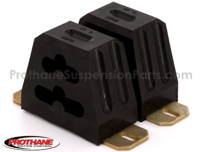
the lower dark grey block would be a couple progressive bump stops like this;
PR191310BL_lg.png

the bumpstops have a lot of "give" so that the body could lift off of the frame in a "frame flex" situation ... they would basically replace the steel holddown springs of the military flex mounts.

i plan to locate the box with a panhard bar as well as two "crash-links" in driving direction
i would actually use the exact same torque links that i plan to use at the (air ride) rear axle ... this way i have parts interchangeability ;)

what do you guys think about this idea ?!?
 
Last edited:

RoosterBooster

Observer
ntsqd; good points ;)

i guess i was overthinking it :coffee: ....
after looking at Skifreaks (excellent!) Australian PDF link i will most likely stick with the very simple "diamond pattern 4-point" ....
considering that a frame twists into a (very flat) X shape in a articulation situation the 4 point makes the most sense (for a box of my size) ...
has anybody any experience with large "Lord" (3D) center bonded rubber mounts like this ??? ;

http://www.westernrubber.com/all/products/lord-mounts/centerbonded/

the large "Safetied Tubeform Series" seems to be perfect fort the front/rear mount
 

ntsqd

Heretic Car Camper
Until now I've never been able to articulate why I'm not fond of the "diamond" mounting pattern. I'm still not sure that I can get this across, but I'm going to try.
First assumption: looking at ladder frame simple torsion - no bending involved. With this the two lateral mounts need to be centered between the end mounts. The tolerance for slightly off-center is half of the compliance of those lateral mounts. This also assumes that the torsional stiffness of the chassis is constant between the end mounts. If it is not, and there are a lot of things that can affect this, then the lateral mounts will need to move to the "neutral" point on the chassis. Predicting that location without a lot of trial and error and/or some sophisticated CAD modeling won't be easy.
Assumption modification: Add in some bending of the rails. Now, no matter what the torsion is like, those 4 points will not be in the same plane. This is just not possible. The amount of bending that can happen without causing trouble is the vertical compliance of the end mounts.

I've sat on plenty of 4 legged bar-stools that wobbled. I can not recall a three legged bar-stool ever wobbling (well, except for that time in Pioche, but that probably wasn't the stool's fault.... :sombrero:).

What is the problem that a 4 point mount is trying to solve that a three point mount won't solve? I can't see it, but I can't claim to have huge experience in this area either.

Was it me, I'd study how the U.S. 2.5t and 5t military trucks have been doing it since WWII and copy that design. It may not be elegant, but it works and that is most important. It adds section modulus and some torsional stiffness to the chassis while also allowing the chassis to twist without causing trouble.
 

RoosterBooster

Observer
LOL ... oh yes, i agree; a 3 legged barstool can wobble ! :coffeedrink:

what draws me to the 4 point (or 2+2 point) is the location of the mounts;
the two (massive!) main center mounts would be right in between the trailing arm mounts & air bags of the rear suspension.
the main weight of the box would go almost direct into the suspension mounts ... virtually bypassing the frame.
this is also a area where my current box floor design would be very strong (walls, heavy steel wheel tubs, etc) and has some unused space (SRW) for large mounts and bracing.

the front and rear mounts could be lighter and more flexible (i`m thinking of using large bonded "Lord" mounts; 3D flexibility plus misalignment tolerance)

disadvantage; high misalignment in the cab to box opening (i will need a large rubber Unigrip accordion seal)
 

RoosterBooster

Observer
ntsqd; ok, you win ;)

after lots of reading and also studying some of the videos and a long discussion with my brother (who actually has a master degree in automotive engineering)
i have to agree with you that the 4 point has some major drawbacks over the 3-point (at least for my application).

the biggest one is the location of the main mounts (that "guide" the box);
at first glance it looks very attractive to have them right at the rear suspension mounts (basically bypassing the frame)
but as my bro pointed out on a MD/HDTruck style suspension (with very limited axle articulation) this is subjecting the box to very violent side to side movements when the rear tires go over a large bump or drop in a hole
(as can be seen in the Unicat video that was posted earlier in this thread).
locating the main mounts along the frame more or less centered between the axles is reducing this motion drastically
however, this is subjecting the frame to more stress so great care has to be taken to introduce the forces of the main mounts into this area of the frame.

my (hopefully soon to start) project will have straight 10.125 x 3.062 x .312" frame beams (257 x 77.8 x 8.0 mm for the metric guys)
it is a MDT so the frame is "only" HSS and not heat treated (as is basically standard with HDTrucks)
this means i have to spread the load over a larger area (more bolts) backed by a rather large flanged cross-brace to avoid any kind of frame webbing flex.
so my bros advice is clearly towards a 3-point (with the rear trunnion at mid frame level and as close to the rear axle as possible).
right now we are looking into a idea to may use two rubber cushioned trunnions (one integrated into the suspension mount cross brace and one towards the end of frame)
to may spread the punctual load in the rear over a larger area.
i will post a sketch later on ...
 
Last edited:

RoosterBooster

Observer
stumbled over some interesting pics ;)

this pics show how much flex a heat treated frame can tolerate :Wow1:

Peterbilt2.jpg

darn, and i was thinking i had my Pete in some high flex situations :smiley_drive:

Peterbilt3.jpg

judging by the yellow oil pan i would say the only thing that keep`d the Pete from rolling completely was the weight of the bigblock C15 on the front axle

...
 

fisher205

Explorer
Over the years the only time I've seen articulation like that is when someone raises their dump bed on uneven ground. I wish I had taken pictures of some of the twizzler frames that are left from that type of poor judgement.
 

dhackney

Expedition Leader
ntsqd; ok, you win ;)


my (hopefully soon to start) project will have straight 10.125 x 3.062 x .312" frame beams (257 x 77.8 x 8.0 mm for the metric guys)
it is a MDT so the frame is "only" HSS and not heat treated (as is basically standard with HDTrucks)
this means i have to spread the load over a larger area (more bolts) backed by a rather large flanged cross-brace to avoid any kind of frame webbing flex.
so my bros advice is clearly towards a 3-point (with the rear trunnion at mid frame level and as close to the rear axle as possible).
right now we are looking into a idea to may use two rubber cushioned trunnions (one integrated into the suspension mount cross brace and one towards the end of frame)
to may spread the punctual load in the rear over a larger area.
i will post a sketch later on ...


The highest frame stress point in your design will be at the back of the cab, so it will help a lot if you put the pivot there. Downside is then the cab to box junction will require a very flexible connection which can lead to more potential leakage. If you put the pivot at the rear to make the cab/box connection easy, you add maximum stress to the longitudinal point on your frame that is already the most stressed point. Everything is a compromise.

As previously mentioned, the 3 point payload suspension will put your entire payload weight onto the frame in only two longitudinal locations. If you keep your payload to a reasonable level (do not use our truck as an example of "reasonable"), you should be OK with your size and weight capacity frame.

In terms of "Will this 3 point payload suspension work with my frame and payload?" keep in mind that it's not just static load capacity, but also long-term stress and repetitive loading/unloading of the frame between those two longitudinal points. In this case, we are an excellent example of a potential negative outcome. :) If you have even the slightest trepidation, sleeve your frame now while it's still open and accessible.

Doug
 

Forum statistics

Threads
185,826
Messages
2,878,609
Members
225,393
Latest member
jgrillz94
Top