Sprinter 4WD Conversion Idea, GMT-800 IFS.

luthj

Engineer In Residence
If I had a decent shop, and a CNC plasma cutter, I would just tear my van down on a lift/stands. Make a few mockups with wood and cardboard, and do a Frankenstein with plasma cut plate. Wouldn't be pretty, but I would have something rolling in a month or so. I built a half scale open cockpit racecar that way in a few months on nights/weekends back in college. The modeling was too slow, so I only used the software to setup my suspension hard points, and everything else was mocked up on a dumpster salvaged folding table! We also welded it up on the table. Which explained the slight frame warp. It was a banshee though, 600cc Suzuki 4 cyl and race slicks...

If I had OEM parts models this would be a lot easier, but such is life!
 

Len.Barron

Observer
That's the tough thing about working with a vehicle that was designed overseas, getting any real useful engineering data is damn near impossible and those that have it aren't going to just share it in the open. Compare that to something like the GM Upfitter site where they publish frame drawings (granted they aren't build quality drwgs) but you get a hellavu head start from working that out from scratch..
 

Paddy

Adventurer
While it's tedious work, mocking everything up, connnecting all the parts always shows something that you would have otherwise missed, it's also a great opportunity to clean and paint older parts...none of this is a valuable as standing in front of it with your hands on you hips and staring at it...I'm convinced that is the magic..
Funny how that staring at it bit does matter and the fact that cars get designed and built in cad is amazing. My friend works in the auto industry and he described an interesting process where they use electrified gloves that have sensors and VR goggles to manipulate parts, such as a gas tank, that may be theoretically impossible to install in cad, but in real life sometimes there is just enough room, or not, so they use this VR world to manipulate the cad files “by hand”.
Made a lot of sense.
 

luthj

Engineer In Residence
Put the Tbar and A-arm on the floor. GM has some interesting angles. The Tbar is not parallel to the arm pivot. It angles in about 2.75" over its length. GM also has the the lower pivots non parallel (left to right). Instead the front is narrower than the rear. With my current placement the lower pivots are parallel. This results in the rear of the Tbars being too narrow for the factory carrier. Right now its about 28" center to center, with the factory carrier at about 33.5" center to center.

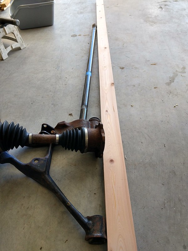
IMG_20190223_111007884_HDR by J Luth, on Flickr

My options are to narrow the factory Tbar carrier to fit. Or to move the front pivot inwards by 1" or so per side. The downside to this is that it introduces a small angle between the bushings and subframe. Bending the plate to align is not really an option with the subframe being mostly parallel planes. Moving the front bushing inwards would improve my ackerman slightly.

I am not sure why GM would use non-parallel lower pivots axis in this application? I don't see it providing any useful geometry changes either. It may just have to do with convenient mounting locations.
 

luthj

Engineer In Residence
It will take a 1" shift (per side) of the front lower bushing/pivot point. This equates to a 3 degree (per side) change in the axis. The outer tie rod joint shifts forward 0.7". Unfortunately this also means a 3 degree increase in the static CV angles. Not sure if this is acceptable or not, so if I go this route the diff may need to move.

Shortening the Tbar carrier is not difficult, and I think there is enough room for the 3 degree angle on the keys.

1550948509967.png

1550948785604.png
 

b dkw1

Observer
The angled lower mounts also screw with your anti-dive numbers. I had forgotten about them not being parallel till I read this. Now I remember my buddy cussing at his 1500 when he was building the arms for it LOL. He ended up redoing the rear mounts to match the fronts.
 

luthj

Engineer In Residence
Hmm. I think I am leaning towards shortening the carrier. I made a few changes to my carrier drop bracket for a shortened carrier. I am also questioning weather its worth having rubber bushings on the carrier mounts at all. The little bit of rubber on the factor ones isn't going to do much. Obviously they went away from the big rubber bushings used on the 1500 because they can't handle the extra weight and abuse. Doing away with rubber bushings for NVH concerns means I can weld a trailing beam between the trans crossmember and the Tbar carrier. Which would make a very convienient place to put a light duty skid plate.

1550953742792.png
 

luthj

Engineer In Residence
After some thought, I decided to incorporate GMs non-parallel pivots. It was a bit fiddly, but I think everything clears now. Its going to be a bit tough to pull the bushing bolts down tight the first time, as the surfaces as 3 degrees from orthogonal.

1551197771406.png

A fair bit of material needed removed to clear the front mount as, the front leg of the A-arm is a nearly straight run from the BJ. Of course with the wheels moved foward a bit, the subfram mounting holes may interfere with some lateral structure. Grrr. I won't know for sure until I drop the factory subframe for measuring.
1551198290262.png
 

Attachments

  • 1551197850061.png
    1551197850061.png
    58.3 KB · Views: 9

luthj

Engineer In Residence
I made a few adjustments. The wheel flange width is now 71.26" wide. I widened the LCA pivots by 1" total, and adjusted the angle so the torsion bars line up with the factory carrier. I moved the UCA pivot out about 3/8". The clearance hole in the sprinters frame will be much small now.

Supposedly the factory suburban wheels are ET 28. Not sure if believe the internet though. That would put my track width at 69". That's too wide for my fenders, with the factory track being around 65". GM uses the same wheel pattern on the savanna and other 2500/3500 series trucks. I see offsets around 120mm. So with a 60mm spacer, I can set the track width around 66". Assuming the wheels clear the suspension of course.

The tie rod placement is just about perfect with the 3/4" offset rack spacer. I still need to design it, hopefully I can retrieve my spare rack this weekend, and measure it.

The bumps steer is very sensitive to tie rod position. So I anticipate needing to adjust the rack by plus/minus 3/8" during the final assembly. So I need to figure out how I want to accomplish this. I need some angular adjustment to position the steering shaft as well, so it may be best to just order a couple different brackets with different placement, and include slots of the angular adjustment?
 

Wyuna

Observer
A lot of thought and design is going into this.

In hindsight, it might of just been easier to transfer everything out of a wrecked 4x4 sprinter when you were here in Australia.

Although i am very keen to see the end product and using easily available parts, makes it easier if something breaks
 

luthj

Engineer In Residence
A lot of thought and design is going into this.

In hindsight, it might of just been easier to transfer everything out of a wrecked 4x4 sprinter when you were here in Australia.

Although i am very keen to see the end product and using easily available parts, makes it easier if something breaks

I nearly bought the parts to do the conversion in Aus. But cost, and some unknowns about fitment stopped me. The MB front diff doesn't clear the 5 speed auto, so I would need to modify some stuff (hard to do when you live in a van). There was also dealing with the parts that I would need to ship back separate from the van.
Knowing what I know now about the NAG1 and jeep Tcases, I would have more seriously considered the factory front axle assembly. Though finding parts for that is essentially impossible in north america. If the ring gear wore out or failed, I would be stuck with a $$$$ bill with international shipping. While with the GM parts its just a phone call away in North America, and a DHL box with new parts everywhere else.


I did some more measuring. I am going to lengthen the wheelbase by about .75". This will allow me run a larger tire if desired. It also places the 8x mounting bolts and engine mount towers in ideal locations. Not my photo below, but you can see the factory tire placement. The front plastic bumper is much easier to trim. I have a steel bumper with better clearance though.

attachment.php


I think I have decided to make the rack mounts in two pieces. I will put a slot for about 1/2" of vertical adjustment. I will use spacers under the rack mounting bolts to adjust steering shaft angle.

One issue I noticed is that the steering rack can't be removed with the tie-rods in place. At least not with the Diff installed. Not a huge deal, but will add some complexity to that service. Currently the sprinters rack can be dropped with the rods in place. Though it required removing the LCA support plate, and some serious Yoga.
 

luthj

Engineer In Residence
I saw a suburban build with coilovers. That got me thinking, and I may be able to modify the shock tower to handle the load. I am not certain I can get a coilover to clear the UCA though. Does anyone have access too, or can point me toward a tech catalog for one of the coilover MFGs? They simply don't post tech specs for their products. Bushing/bearing dimensions, external dimensions etc. I can't even find total length for some of them!


It looks like I have room for up to about 3.1" OD spring. The stock lower shock mount is 1.3" wide, and the bolt is ~13mm. Which roughly matches the bearing lowers on the fox 2.0 coilovers. I see some kits from BD that use a fox factory series, but I think that needs a new upper Arm to clear the larger spring?
https://4x4.fatbobsgarage.com/chevr...057.aspx?utm_medium=cse&utm_source=googlebase

1551452093511.png

ck_741FDSC-742FDSC.jpg


Springs for the fox 2.0 (2.5" ID spring) are available up to 700lb/in. That should be enough, but I need to do some maths.


Coilover units are as cheap as 200$ each (plus spring). It might be worth it for the better ground clearance (No Tbar carrier). I don't particularly wan't to mess around with the fuel tank for a carrier bracket either. The big question is making an upper mount that can take the very significant loading. I don't have much meat to anchor to, as the CV clearance holes are in the same rough position. Though I can extend a leg up to the corner brace for the sprinters factory strut boss.
Fox-2.0-Remote-Reservoir-Coilover.jpg
 
Last edited:

luthj

Engineer In Residence
Some rough math puts the desired spring rate 800-900 lb/in with 5" of shock travel. Preload would be in the .7-1" range. I see springs up to 1000lb/in, so I have some wiggle room.

For refference my van will have about 3700-4000lb on the front axle. Thats a corner weight of 1850 minimum. Unsprung weight is about 65lbs for wheel/tire, and 50-80lbs for suspension/brakes. The motion ratio for the GM A-arm is about 0.59:1. My current model has the shock at 13 degrees from vertical, maybe a touch more in the lateral plane.
 

luthj

Engineer In Residence
Spent a bit of time reworking the model for the proposed coilovers. I don't see any reason why a 2.0" coilver with 3.5" OD spring wont' fit. At 5"+ of bump the upper arm would just barely kiss the spring. Good enough for me!


502546

There is still plenty of clearance for a longer shock assembly. Not much point with only 8-9" of travel with the factory CVs anyways. I have one through bolt going through the vans frame rail, and there is enough space that I can put a couple small bolts into the strut brace if needed. I dont think they will be. The shock is at around 17 deg from vertical, so the non vertical component of the strut load will be minimal. There are 3-4 companies that make a coilover that should fit.

502548

There really isn't much room for the GM bumstop. I could do away with the progressive damper part, and use a rubber bushing on the shock shaft. Then retain the final hard-stop. Or maybe remove it completely. That would reduce the weight and complexity of the subframe. I would guess the coilover can handle it.

502552

Axle clearance is close, but doesn't drop under 1/4" at full lock/bump.

502554

Based on my measured CV angles, this is max bump. Assuming the upper BJ doesn't bind. That is a lot of bump. 5.25 from "static", with 3.75" droop. 9" is good stuff. I am using my max CV angles as 20 deg for the inner, and 20 deg (plus 28 for steering) on the outer.

502555

Based on my model 9" of wheel travel equals almost exactly 5" of shock travel. I should be able to get most of that, but bump and droop stops will eat about half an inch really.
 
Last edited:

Forum statistics

Threads
185,828
Messages
2,878,635
Members
225,393
Latest member
jgrillz94

Members online

Top